Motor Timing with Pamco Electric Ign. & TC bro’s PMA kit

TwinLewi

XS650 Addict
Messages
156
Reaction score
134
Points
43
Location
Melbourne Australia
Hey there guys and gals,
Hope all repairs and rides are going sweet. I have been up to a lot on my 73 TX650.
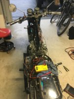
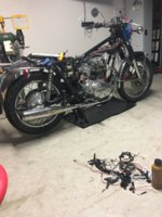
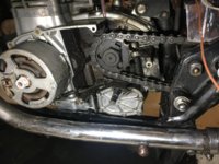
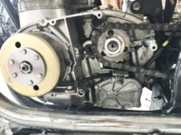
Re wiring the whole thing front to back and just installed a new PMA Kit from TC Bro’s (Permanent Magnet Alternator). When I received this bike it had the original points system removed and has what appears to be a High output electronic Ignition. Not sure on brand like Pamco or not. I have installed the PMA kit. I have rotated the rotor (crank shaft) counter clockwise when removing stock stator and rotor. When installing the new assembly I rotated rotor to the right while tightened a bit. Also moved it both ways to check for clearance or anything that may be rubbing after install. Need to know if that was a bad mistake to rotate crank clockwise by a turn or two. Secondly I need help getting this timing sorted. I think having electric ign. (No points system) always gives me perfect timing. Is that true? It must be off though. I think it is time to buy a timing gun! Hope I have supplied the right info and asked the right questions. Learning all the time and love me hands dirty. Thanks for your time and knowledge everyone as always! Enjoy the knees in the breeze.
lewi.
 

Attachments

  • 39B6E633-71D6-4EDB-A2E3-FBCA42399E22.jpeg
    39B6E633-71D6-4EDB-A2E3-FBCA42399E22.jpeg
    195.3 KB · Views: 199
  • 3972BC1C-3B63-469E-A98B-BF6A8C1697F5.jpeg
    3972BC1C-3B63-469E-A98B-BF6A8C1697F5.jpeg
    181 KB · Views: 166
  • 4A982E69-4609-405B-9985-CBA1C758A4A1.jpeg
    4A982E69-4609-405B-9985-CBA1C758A4A1.jpeg
    219.5 KB · Views: 175
  • F3E055B6-33BD-4942-A159-573462246737.jpeg
    F3E055B6-33BD-4942-A159-573462246737.jpeg
    210.3 KB · Views: 191
For timing/ locating TDC,
I will start with marking on the lower flange of the side case behind the inspection cover. there is a notch on the case. Right side of notch for TDC.
Second I can remove the spark plugs and rotate the crank shaft so that the piston reaches the highest point of in the stroke. Then mark a line on the new rotor to where the marker I have on the flange/ case. Also making .500 inches to the left of TDC to give me my 15° mark. Sound about right? I posted this then studied some more so here I am.
 
Determining tdc by looking or poking through the spark plug hole is not exactly a precise method. For several degrees of crankshaft movement around tdc, the piston hardly moves.
Using some kind of positive piston stop that contacts the piston 30 degrees or more btdc/atdc, and marking those positions precisely is a first step. Then actual tdc is exactly between those marks. From that actual tdc, you can then measure out your idle advance and max advance marks.
As I have posted before, it is preferable to make all marks at the largest possible radius (I.e on PMA rotor periphery) for best precision and access. For me, that would be somewhere around 12-o-clock, on the inside edge of rotor periphery, with corresponding marks on stator plate or crankcase, as close to rotor as possible, to avoid any parallax error when using a timing light. This means one will have to remove the large LH engine cover for timing checks and adjustments, not just the small inspection cover. Which really is not a big deal when using electronic ignition. Or maybe install a new small inspection window or removable inspection cover.
Not as "easy" as you described it, but the only way to get a precise result. Look at degree wheels used for timing performance V8 engines during assembly (camshaft and ignition timing) Those degree wheels are 10 inch diameter, or larger, in order to achieve exact timing figures.An XS650 PMA rotor is maybe 4 inches/ 100 mm diameter, so 1 degree is less than 1 mm on the curcumference/ periphery. Making any timing marks on an even smaller radius makes them less precise.
 
Couple caveats, cuz I've been wrastling this monster on the Vape install thread.
The advance timing is more important than the starting or retarded position. (well mostly.)
If you are using the mechanical advance a couple of things about how it wears tend to increase the range between full retard and full advance as it gets older. So your retarded position can be perfect, and the advance TOO advanced. This can hole a piston.
Careful with stop rods in the spark plug hole when rotating the crank a valve head can contact that rod. That can get ugly fast.
Perfect timing for each engine, modifications, fuel, and operating conditions will vary, so it's a bit like jetting, some experimenting may be result in the best timing for your use. If I had no marks I'd slowly advance the timing till it started to kick back when starting then back it off a bit and call it good, If you aren't after every last bit of horse power slightly retarded timing tends to make for a mellower running motor.
Agreed with arctic that 4" diameter means a degree is a pretty small distance. IMHO why crank timed is a better method, the cam wanders around quite a bit with chain drive.
 
Gary,
Maybe backing off the valve adjustment screws all the way will reduce valve lift enough to avoid interference between valves and piston stop?
 
Couple caveats, cuz I've been wrastling this monster on the Vape install thread.
The advance timing is more important than the starting or retarded position. (well mostly.)
If you are using the mechanical advance a couple of things about how it wears tend to increase the range between full retard and full advance as it gets older. So your retarded position can be perfect, and the advance TOO advanced. This can hole a piston.
Careful with stop rods in the spark plug hole when rotating the crank a valve head can contact that rod. That can get ugly fast.
Perfect timing for each engine, modifications, fuel, and operating conditions will vary, so it's a bit like jetting, some experimenting may be result in the best timing for your use. If I had no marks I'd slowly advance the timing till it started to kick back when starting then back it off a bit and call it good, If you aren't after every last bit of horse power slightly retarded timing tends to make for a mellower running motor.
Agreed with arctic that 4" diameter means a degree is a pretty small distance. IMHO why crank timed is a better method, the cam wanders around quite a bit with chain drive.
Determining tdc by looking or poking through the spark plug hole is not exactly a precise method. For several degrees of crankshaft movement around tdc, the piston hardly moves.
Using some kind of positive piston stop that contacts the piston 30 degrees or more btdc/atdc, and marking those positions precisely is a first step. Then actual tdc is exactly between those marks. From that actual tdc, you can then measure out your idle advance and max advance marks.
As I have posted before, it is preferable to make all marks at the largest possible radius (I.e on PMA rotor periphery) for best precision and access. For me, that would be somewhere around 12-o-clock, on the inside edge of rotor periphery, with corresponding marks on stator plate or crankcase, as close to rotor as possible, to avoid any parallax error when using a timing light. This means one will have to remove the large LH engine cover for timing checks and adjustments, not just the small inspection cover. Which really is not a big deal when using electronic ignition. Or maybe install a new small inspection window or removable inspection cover.
Not as "easy" as you described it, but the only way to get a precise result. Look at degree wheels used for timing performance V8 engines during assembly (camshaft and ignition timing) Those degree wheels are 10 inch diameter, or larger, in order to achieve exact timing figures.An XS650 PMA rotor is maybe 4 inches/ 100 mm diameter, so 1 degree is less than 1 mm on the curcumference/ periphery. Making any timing marks on an even smaller radius makes them less precise.
I agree with you. Just removing a spark plug and rotating doesn’t seem accurate enough. I was going to also remove the cover plates on exhaust and compression side to watch them hit their stopping points. I was watching the video I found on the forum from “Bill’s Valve adjustment/ timing videos”.
I just had my valves adjusted two rides before the mods. I would presume they are still fine but I still should check. I am a newbie with this and it is my first time for timing and understanding the re wiring process.
when you mentioned “From that actual tdc, you can then measure out your idle advance and max advance marks”. I am not % on what that means. Is that just the two marks I need to make on the rotor and case? So new. Sorry. Then you mentioned one would have to remove the LH engine cover and not just the inspection plate. I currently have the left side case off that shows rotor, chain and sprocket. So keep that off during the process? I should also have valve covers off? Thank you so much for the knowledge.
 
timing rules.jpg

These dimensions were measured on the stock stator frame as seen above. They will change depending on distance from crank center you make your marks.
Early (1970) 10 to 15 BTDC initial, 38 full advance
Late model (TCI) timing 15 degrees BTDC initial, 41 , plus or minus 1.5 degrees, BTDC advanced.

These dimensions were measured on the stock stator frame as seen above. They will change depending on distance from crank center you make your marks.
timing2.JPG
 
Gary,
Maybe backing off the valve adjustment screws all the way will reduce valve lift enough to avoid interference between valves and piston stop?
My "fix" was to make a sliding stop so I don't have to turn crank the long way around.
20200111_134558.jpg 20200111_135059.jpg 20200111_135138.jpg
You still need to be sure the piston you are checking is on the "firing" TDC.
 
Converting degrees to distance is fairly simple. Lets say your rotor diameter is 4" as was suggested above. the circumference is 12.5" (D X Pi). 12.5" divided by 360 (number of degrees in a circle) is .035". Ain't much is it? Each degree is about the gap of a spark plug. So, per Gary's numbers, 15° is .525" ( .035" X 15°). That's your fire mark...BTDC. Full advance at 38° is 1.33" BTDC
Since a stock rotor is just under 4".... you can see this closely matches Gary's numbers.
 
Last edited:
Determining tdc by looking or poking through the spark plug hole is not exactly a precise method. For several degrees of crankshaft movement around tdc, the piston hardly moves.
Using some kind of positive piston stop that contacts the piston 30 degrees or more btdc/atdc, and marking those positions precisely is a first step. Then actual tdc is exactly between those marks. From that actual tdc, you can then measure out your idle advance and max advance marks.
As I have posted before, it is preferable to make all marks at the largest possible radius (I.e on PMA rotor periphery) for best precision and access. For me, that would be somewhere around 12-o-clock, on the inside edge of rotor periphery, with corresponding marks on stator plate or crankcase, as close to rotor as possible, to avoid any parallax error when using a timing light. This means one will have to remove the large LH engine cover for timing checks and adjustments, not just the small inspection cover. Which really is not a big deal when using electronic ignition. Or maybe install a new small inspection window or removable inspection cover.
Not as "easy" as you described it, but the only way to get a precise result. Look at degree wheels used for timing performance V8 engines during assembly (camshaft and ignition timing) Those degree wheels are 10 inch diameter, or larger, in order to achieve exact timing figures.An XS650 PMA rotor is maybe 4 inches/ 100 mm diameter, so 1 degree is less than 1 mm on the curcumference/ periphery. Making any timing marks on an even smaller radius makes them less precise.
I need to go buy a degree wheel and timing gun. Is there any specific degree wheel I need?
 
View attachment 158728
These dimensions were measured on the stock stator frame as seen above. They will change depending on distance from crank center you make your marks.
Early (1970) 10 to 15 BTDC initial, 38 full advance
Late model (TCI) timing 15 degrees BTDC initial, 41 , plus or minus 1.5 degrees, BTDC advanced.

These dimensions were measured on the stock stator frame as seen above. They will change depending on distance from crank center you make your marks.
View attachment 158729

thanks for the explanation and photo’s. What doesn’t the F and the T stand for? So I need valve covers off, rotate rotor and watch intake valve move to a stop, then see exhaust valve move and come to a stop and watch for piston come to the top of its stroke to get TDC?
Place my degree wheel on the crank shaft and make my marks?
 
My "fix" was to make a sliding stop so I don't have to turn crank the long way around.
View attachment 158730 View attachment 158731 View attachment 158732
You still need to be sure the piston you are checking is on the "firing" TDC.
Converting degrees to distance is fairly simple. Lets say your rotor diameter is 4" as was suggested above. the circumference is 12.5" (D X Pi). 12.5" divided by 360 (number of degrees in a circle) is .035". Ain't much is it? Each degree is about the gap of a spark plug. So, per Gary's numbers, 15° is .525" ( .035" X 15°). That's your fire mark...BTDC. Full advance at 38° is 1.33" BTDC
Since a stock rotor is just under 4".... you can see this closely matches Gary's numbers.

Thank you sir. That is some great info. I will measure my TC Bros Rotor, do the math and see if I am right.
 
Silly question but I am sure timing is off.
If I removed old Stator and rotor which spun the crankshaft, installing the new rotor. Would that throw my timing off on the ignition as well? It is like the pamco electric ignition.
 
"TwinLewi, What doesn’t the F and the T stand for?"
T is for TDC F is for fire. Starting or retarded timing. The mark furthest left is the advanced timing mark and is the most critical setting to have right.

"So I need valve covers off, rotate rotor and watch intake valve move to a stop, then see exhaust valve move and come to a stop and watch for piston come to the top of its stroke to get TDC?
Place my degree wheel on the crank shaft and make my marks?"

Well that's the short version. On the "other side" the intake valve opens just as the exhaust closes so the valve springs kind of "self center" the crank at TDC.
See all our comments about having to use some sort of a rod through the plug hole and making marks at some fixed distance either side of TDC then measure and mark TDC exactly halfway 'tween those marks.
 
Silly question but I am sure timing is off.
If I removed old Stator and rotor which spun the crankshaft, installing the new rotor. Would that throw my timing off on the ignition as well? It is like the pamco electric ignition.
Your new rotor has no keyway and will install in any old spot, so the TDC mark you make is good ONLY until you take the rotor off again.
But no the camchain keeps the crank, cam and Pamco in correct alignment even with the rotor off.
 
Last edited:
I need to go buy a degree wheel and timing gun. Is there any specific degree wheel I need?
No, you do not need a timing wheel. I just mentioned it to point out the need for making any timing marks at the largest possible radius.
What you basically need is some kind of piston stop or position indicator, a tape measure and a sharpie pen (or a scriber) to mark the PMA rotor. And possibly a thin piece of wire or welding rod to make a pointer to attach to the crankcase, acting as a fixed reference mark.
 
Okay here is a photo of what I got.
Would you agree .500 inch is 12.7mm?

Last two pictures is a short paragraph from instructions thatTC Bro’s Supplied with the PMA.
 

Attachments

  • A99C2D6E-5542-4575-9B93-CF5A08BBAB40.jpeg
    A99C2D6E-5542-4575-9B93-CF5A08BBAB40.jpeg
    171.6 KB · Views: 234
  • 0ACDB27B-4086-4F86-898E-EC3AD9B5D531.jpeg
    0ACDB27B-4086-4F86-898E-EC3AD9B5D531.jpeg
    182.9 KB · Views: 234
  • 8EC1B397-0D90-4FFF-9F1C-40906930F02D.jpeg
    8EC1B397-0D90-4FFF-9F1C-40906930F02D.jpeg
    146.2 KB · Views: 201
  • 2AE0AD93-F07A-4B3C-9F55-24E1E6CB31C6.jpeg
    2AE0AD93-F07A-4B3C-9F55-24E1E6CB31C6.jpeg
    163 KB · Views: 215
If you provide the exact distance from crankshaft center to the horizontal top edge of the inspection window, I can verify that for you. It does seem close when just estimating this distance.
However, I still have reservations regarding the way TC Bros tell you to determine TDC. It is not very precise.
Another thing that comes to mind when looking at your pics, is the height of the horizontal portion of the cover, where you have made your marks. If you were to file or machine it down to just below the 2 holes in the rotor, you would gain some more precision (i.e.resolution) because your timing marks will be at a larger radius, and you can also get the rotor and cover marks closer together, minimizing any error that way as well.
 
Last edited:
Another thing that comes to mind when looking at your pics, is the height of the horizontal portion of the cover, where you have made your marks. If you were to file or machine it down to just below the 2 holes in the rotor, you would gain some more precision (i.e.resolution) because your timing marks will be at a larger radius, and you can also get the rotor and cover marks closer together, minimizing any error that way as well.
While I agree with that in principle... it'd be much easier to just move the marks to a point farthest away from the crank center. And mind what Gary said above... full advance is much more critical than the initial "F" mark. You really should include that.

A99C2D6E-5542-4575-9B93-CF5A08BBAB40.jpeg
 
If you provide the exact distance from crankshaft center to the horizontal top edge of the inspection window, I can verify that for you. It does seem close when just estimating this distance.
However, I still have reservations regarding the way TC Bros tell you to determine TDC. It is not very precise.
Another thing that comes to mind when looking at your pics, is the height of the horizontal portion of the cover, where you have made your marks. If you were to file or machine it down to just below the 2 holes in the rotor, you would gain some more precision (i.e.resolution) because your timing marks will be at a larger radius, and you can also get the rotor and cover marks closer together, minimizing any error that way as well.

Okay I will take a measurement and get back to you. Mind I am in Australia and there is a massive time difference. It is 10:50am. I was up till 3:30am working on the old girl. Finished the re wiring of the whole bike. So exciting.
 
Back
Top