Pma and safety relay

londoncabby

XS650 Addict
Messages
100
Reaction score
117
Points
43
Location
Essex England
I have just fitted a pma system to my 78xs and as some of you may know there is nowhere to connect the yellow safety relay wire, at the moment I'm running it without it but at some point I would like to reconnect it I've heard you can connect the yellow wire by splicing it in to one of the white wires going to the reg/rectifier with a diode in the the wire so my questions are do I need to put a diode in and if so which way round? does the positive go to the white wire or the yellow,I did try the search facility but couldn't find the right answer.
 
Unfortunately no I still haven't got the safety relay sorted I bought some diodes and that's as far as I got! If anyone has got some info on this subject it would helpful as it sounds like it's not just me who cringes every time they press the electric start button!!
 
Last edited:
well that's an AC relay so it shouldn't matter? you are just trying to reduce the amount of energy going into the relay coil as the stock yellow from the alternator is a short coil producing ML 6 volts AC something like that. I haven't done this one but mebbie ohm out the relay coil, add in a resistor of about the same ohms in the line to the reduce the voltage the coil sees.
 
if you use a voltage divider the resistance of the relay coil will be included in one leg of the divider and it it's low enough (i don't know what it is), you will have to use big high wattage resistors to get the voltage you want. If you have a single nominal 12v output from the pma, you could use a 7806 voltage regulator, one lead goes to ground, one is your 6v out, and the other goes to any 12v that's present only when the pma is churning. You mention "one of the white wires" on the pma. if you have an arrangement of three phases like in the stock generator, only using a permanent magnet for the field, in the stock system the yellow ties to the common point of those three coils. If you can measure that and it's around 6v, just tie the yellow in there
 
I was looking at the diagram for that relay. There's a resistor that latches one of the pair on. It forms a voltage divider with that coil. It is 45 ohms and the coil wants to see 6v so it makes sense that the coil is also about 45 ohms. The yellow has to power two coils in parallel so it becomes 20 ohms. A 20 ohm resistor with 6v across it would dissipate 1.8 watts, so a 20 ohm, minimum 2 watt resistor would do the job. The connection would be 12v -> resistor -> yellow wire to relay. Other side of both coils to ground as usual. No other resistor needed

I was looking at ways to try and concoct a neutral (where yellow wire comes from) like the stock generator has but if there is one it hasn't dawned on me yet. The stock generator has the star configuration, not the delta, judging by it's diagram. The total swing is 12v so the neutral would be 6v above ground and be steady because of how the phases move around it -- always an equal area above and below it or something

generator windings
https://infinispark.com.au/7-facts-you-need-to-know-about-neutral-wire-in-a-3-phase-circuit/
 
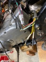
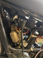
I have a 1975 (lights not controlled by the safety), and Im using a HHB PMA. So, two yellow wires coming from the generator going to the regulator. I attached my ohm meter to the yellow and black wires coming from the safety relay, and I got about 18.8 ohms. so if I assume my relay only has to power one coil, and then put a 20 Ohm resistor in series before the relay... that should cut the voltage approximately in half. or does my safety relay just take 12 volts.
I don't have a wiring diagram for the relay and I wouldn't want too much current going through it getting it hot. Would I need to do something different?
 
Think both those relays are the same they both act on voltage in the yellow wire as proof the motor is spinning (fast).
 
You confused me gggGary. No doubt I'm a little slow. Now, the motor spinning fast is proof of what? I thought the voltage through the safety relay only allows the starter solenoid to not work. The safety relay only opens and closes the floodgates sorta speak. Making the voltage and current through the safety relay totally independent of the voltage and current going to the starter.
 
Here's what Yamaha has to say.
starter circuit.jpg

Not everyone has read this and a few are a bit confused about the reason for, and function, of the safety relay.
Note it calls out 4 volts as the pull in (open) voltage
So now you are "ahead of the crowd". :sneaky:
 
Would I be doing any harm to my regulator if I splice into one of the two wires(yellow) coming from the pma before the regulator. my hypothesis is that would be borrowing the same potential difference (voltage) from one of the wires coming from the PMA, while drawing very little current due to the high resistance of the resistor in series and the safety relay itself.
operating procedure as follows splicing to yellow wire coming from generator before regulator, put 20-30 ohm resistor in series , connect to yellow wire going to safety relay. Then everything works Maybe?
 
I think it's reasonable to try that. would put a volt meter on the bike before you do it, watch for any changes. Perhaps add a test light to the starter circuit to confirm the relay is acting as it should, check with your hand that it isn't running "hot" after riding for a bit? If all good, call it done
 
Only two yellow, so you have a single phase PMA? they tend to be a rather light on output. gotta watch your watts, no big sound system for you! :laugh2:
 
Would I be doing any harm to my regulator if I splice into one of the two wires(yellow) coming from the pma before the regulator. my hypothesis is that would be borrowing the same potential difference (voltage) from one of the wires coming from the PMA, while drawing very little current due to the high resistance of the resistor in series and the safety relay itself.
operating procedure as follows splicing to yellow wire coming from generator before regulator, put 20-30 ohm resistor in series , connect to yellow wire going to safety relay. Then everything works Maybe?

Here's the best diagram of the relay(s) which resembles the physical layout and is color-coded.
lighting relay.jpg
o

It's shown in the unenergized state. One relay uses normally open contacts and the other uses normally closed contacts as you see. To energize it, 6v arrives on the yellow wire shown. The presence of the 6v is the signal that the generator is running. The 6v opens the relay labeled SR which turns off the started, and closes LR which turns on the lights. As soon as LR is closed, 12v appears on the downstream, lights, side of LR. That 12v is divided by the resistor you see and the resistance of the coil of LR to provide 6v on the coil of LR and keep LR turned on, even if the 6v on the yellow wire goes away. That is why the lights stay on if the engine stops, until you turn off the key. The diode keeps the voltage latching LR on from latching SR on which would defeat the purpose of SR.

The yellow wire(s) coming from the hbb are not to be confused with the yellow wire on the diagram. They are just the same color... Pictures of the hbb that I see appear to have three (not two) yellows coming out, which correspond to the three whites coming out of the stock generator, one for each of the three output phases of the generator. Bottom line, what you need to do is supply a steady 6v to the yellow in the diagram for as long as the generator is turning and only when the generator is turning. And it can't interfere with the operation of the generator. Doesn't matter how you do it. Measure voltages before hooking in of course to not overvoltage the relays
 
Here's the best diagram of the relay(s) which resembles the physical layout and is color-coded.
View attachment 185900 o

It's shown in the unenergized state. One relay uses normally open contacts and the other uses normally closed contacts as you see. To energize it, 6v arrives on the yellow wire shown. The presence of the 6v is the signal that the generator is running. The 6v opens the relay labeled SR which turns off the started, and closes LR which turns on the lights. As soon as LR is closed, 12v appears on the downstream, lights, side of LR. That 12v is divided by the resistor you see and the resistance of the coil of LR to provide 6v on the coil of LR and keep LR turned on, even if the 6v on the yellow wire goes away. That is why the lights stay on if the engine stops, until you turn off the key. The diode keeps the voltage latching LR on from latching SR on which would defeat the purpose of SR.

The yellow wire(s) coming from the hbb are not to be confused with the yellow wire on the diagram. They are just the same color... Pictures of the hbb that I see appear to have three (not two) yellows coming out, which correspond to the three whites coming out of the stock generator, one for each of the three output phases of the generator. Bottom line, what you need to do is supply a steady 6v to the yellow in the diagram for as long as the generator is turning and only when the generator is turning. And it can't interfere with the operation of the generator. Doesn't matter how you do it. Measure voltages before hooking in of course to not overvoltage the relays
His 75 doesn't have the headlight relay.
 
That is correct, gggGary there is no light relay. And only two wires coming from pma. But hugh claims 200 watts. Hope this timing light workspma 2 wires jpg.jpg sr.jpg pma 2 wires jpg.jpg sr.jpg timing light.jpg
 
Back
Top