PMA Install- Voltage too high- 6 wire regulator

ChewsVolt

XS650 Enthusiast
Messages
52
Reaction score
0
Points
6
Location
Marin, CA
PMA Install- Burnt stator

I just installed a PMA, I used a ZX600 stator and reg/rectifier per the how-to by hugh on this site. I used banshee flywheel, plate and Hugh's adapter.
http://www.ebay.com/itm/281073996454?_trksid=p2057872.m2749.l2648&ssPageName=STRK%3AMEBIDX%3AIT
At idle I reach 17.8V (ish) and under throttle get all the way to the mid 19s! I assume bad regulator but want to check my steps first.
In the link you can see it's a 6 wire reg/rect, I just ignored the brown, I think it's for some sort of "swithced on" components. I wired the red (pos) and black (neg) directly to my battery posts. Eventually I will run just a sparx capacitor but wanted to test on battery first.
The other (smaller) issue is that I can no longer get my headlight to turn on. I yanked the stock regulator, rectifier and safety relay. I thought I may need the safety relay to engage the headlight so I plugged it back in, not bolted assuming it's not grounded to frame. Still no headlight.
Anyways any other way to test this regulator? Any way I can swap in a different reg/rec to see if that's the issue? I have a dr650, if the components are super genenric perhaps I can do some local swapping before dealing with shipping junk around. Thanks

Posted via Mobile
 
Last edited:
In order to know how the reg/rec should be wired you need to look at the diagram for that bike. If the reg/rec isn't wired in correctly then you will have all kinds of weird stuff going on.
 
Unfortunately I stink at reading wiring diagrams, but really there's just positive and negative coming off this rectifier right? Here's the original wiring diagram.
20070404082637-0-297.jpg

I stink at reading diagrams, but that looks like Black/yellow is ground and the other 2 are positive, with bascially just 2 different jobs on the bike.
To make things worse this is a universal part with colors different than that diagram, and Cal-tric, who I bought it from can't tell me what the wiring color code of their part is is :wtf:
I am going to experiment with the previously neglected brown wire hoping to make this set-up work. Here's my thinking, tell me if I am dumb.
Assumptions- there's only positive and negative coming out of this unit, one wire is a dupe and can be ignored, unless it's a ground in which case ground it damnit!
The yellows are yellows, hook them up and forget about it.
Testing- with the rectifier's red, black and brwn disconnnected from the charging system, but with test leads from my multimeter on I am kicking through the bike looking at voltage. Previous tests showed red to be positive, and black neg. I am going to test with brown now.
Hookup to battery pos to pos and neg to neg.
Test running voltage.
As long as I don't kick out too much current, or set them up backwards I should not harm my ignition system (points)

Posted via Mobile
 
The other 3 wires on that regulator/rectifier in your diagram are:

White - Battery hot
Brown - Switched ignition hot
Black/Yellow - Ground

The colors used on the XS650s are:

Red - Battery hot
Brown - Switched ignition hot
Black - Ground
 
Along with what twomany said, On your reg you need to splice into one of the yellow wires and run it to the yellow wire on the safety relay.
The safety relay gets a voltage on the yellow wire to trip the relay to turn on the headlight and turn off the starter.
The brown wire to switched power is for reading the battery voltage. The reg uses this reference to tell when the battery needs charging.
The black wire goes to the junction block that hooks to, I assume the dash. It also goes to the ignition switch. I think it supplies power for the ignitor.
I might suggest replacing it with a five wire reg/rec. they don't have the extra confusing wires.
Leo
 
:):):)
Thanks TwoMany! I found another diagram for the KZ and determined the same, I soldered the brwn from my stator to a brwn "switched hot" wire at the fuse box and it's way better! I guess that brown wire is in charge of reading the electric signal for the reg to adjust to (?)
I get about 15V all the time now, at idle or revved high.
Is that too high of a voltage? I will be swapping to sparx capacitor shortly
Why does brown need to be "switched hot"? If I just connected red and brown as they exit the reg wouldn't I get the same result? Or would that create a slow drain on the battery?
Anyways, going to take her for a test ride and see if my carb work (throttle shaft seals) paid off also.

Posted via Mobile
 
Double post -tome, thanks ippy for telling me to look at the diagram, I think I was reading it wrong previously.
Thanks leo for that info, didn't see it on my last post. I am going to try to bypass the safety relay., Eventually I want all new simplified wiring, so I am setting up my basic running system now, be sure it works, then challenge myself with re-wiring. I agree with you on the reg, if the company takes it back I should get a 5 wire, but I already spliced a new connector on it. And I am too honest to not tell them
Is 15v too high for constant charging? I guess we will need to see once the headlight is pulling power how that changes my reading

Posted via Mobile
 
Yes, that high a voltage can burn up a battery. It may even be too high for a cap. Best to be below 14.5 volts. 14.1 or so is even better.
Running the headlight may help but I wouldn't count on it.
Leo
 
There's a couple threads here chasing overcharging. The members found a significant voltage drop on the brown 'switched power' lines, which fooled the regulator into thinking there wasn't enuff voltage, so would overcharge the battery. Try voltage tests at the battery, as well as the brown 'switched power', and see if you have a difference greater than 0.5v...
 
I was thinking that may be the problem, good advice to check it, there's a .8 volt difference!
Can I just run the brown to battery pos?
If not I can clean connections and find the voltage drop.
Thanks guys, this is record fast problem solving for me

Posted via Mobile
 
... there's a .8 volt difference!
Can I just run the brown to battery pos?
If not I can clean connections and find the voltage drop...

0.8v is a bit much.
Don't run the brown to battery pos. It'll keep the reg switched 'on', and drain the battery.
Yep, clean connections, and the switch, maybe even solder the crimped connectors/terminals...
 
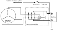
Well, that's the presumption with a 6-wire PMA rec/reg. In the 5-wire rec/reg, the internal regulator shares the same hot lead from the rectifier that goes to the battery, as in this pic. It's likely that your 6-wire rec/reg needs the separate 'switched' line to turn-off its internal regulator.
 

Attachments

  • tech-article-how-motorcycle-works-illustration-01.gif
    tech-article-how-motorcycle-works-illustration-01.gif
    11.6 KB · Views: 1,351
:thumbsup:thanks! I will have time this evening to chase down my voltage drop. Then this bike will be ready for testing as a daily ride!
 
Things are looking better. I eliminated a .3 volt drop in my ignition switch and connectors in my headlight. Voltage fluctuates, gets close to 15 in high revs then drops. Not sure what of that is just multimeter fluctuations.
What are the "light checker" and "reserve lighting" units? I will be wiring up my own harness, i think these things can be omitted from a simple wiring set up (?) Thanks

Posted via Mobile
 
Things are looking better. I eliminated a .3 volt drop in my ignition switch and connectors in my headlight. Voltage fluctuates, gets close to 15 in high revs then drops. Not sure what of that is just multimeter fluctuations.

Great! You're getting closer. With all the wires, connectors, terminals, switches, it's expected that there will be at least some amount of voltage drop.

The fluctuations could be from vibration on something, or the meter's attempt to interpret noise on the line. One trick is to switch the meter to measure AC, then probe. This would reveal the magnitude of the 'noise'.

If you look at the output waveforms of 3-phase alternators, you'll notice that there'll be some ripple on the output. When one leg of the stator goes bad, or a diode in the rectifier fails, there'll be a persistant 'skip ripple' in the output, enough to disturb electronic devices.

An old-school trick to determine if a diode/rectifier failed in old cars, was to turn on the radio, dial to a dead zone, turn up the volume. Listen to the radio while revving the engine. If you heard a staticy/whine noise that followed rpm, you've found a bad rectifier.

Sorry. Slipped into the wayback machine there...
 
The light checker is a device that lights up a light on the dash when light bulbs blow.
The reserve lighting unit lights up the high beam in the headlight at about 1/2 power when the low beam blows.
Yes, they can both be deleted.
Leo
 
Thanks twoMany- I like the old shool recollections, especially if it helps me understand some real world principles. Were things simpler back then? I bet not :) I haven't had time to play this week, I will play with electrical over the weekend. I want to wire in my capacitor and see if it works.
It's the Sparx, originally made for British positive-ground bikes. I don't think that impacts me at all, unless they color code the terminals backwards. After that I think a new wiring loom is going to unlock the next stage of my build. So, eliminating further voltage drop may be better postponed. I need to source a bunch of color coded wire, connectors, similar to OEM if possible, and a good connector crimper. Plan is to have a switch for lights if the cap needs more juice on kick-over. Maybe just re-wire stock ignition?
Thanks Leo, I will look at the diagram and see how I can bypass those units in the meantime...for testing purposes.
In many ways my project is similar to a bobber/chopper in that I want to simplify the bike's components, and rely more on user awareness.

Posted via Mobile
 
... I like the old shool recollections,. Were things simpler back then?

Haha, in their own way, maybe. See if you enjoy this:

http://www.xs650.com/forum/showthread.php?t=31949

... It's the Sparx, originally made for British positive-ground bikes. I don't think that impacts me at all...

Warning, Will Robinson!
Do a google custom search (upper/left box) on "Sparx polarity", read first 3 threads.

... I need to source a bunch of color coded wire, connectors, similar to OEM if possible, and a good connector crimper.

Have a look here:

http://www.xs650.com/forum/showthread.php?p=422889#post422889
 
Thanks for the tips! we're on the same wavelength on the wiring, I purchased a kit from that member just before reading your post! I was able to wire up my capacitor, and get the correct voltage. Unfortunately I found that my 2 week old PMA stator likes to light on fire, so I have other problems to look into now :doh:
So....that's neat. Is there any way user error would cause the stator to burn up?

Posted via Mobile
 
Back
Top