Porting Pics for your Perusal

barncat

XS650 Addict
Messages
359
Reaction score
69
Points
28
Location
Candor NY
been playing with the Dremel. this head is going back on the '73 motor that's getting top end work for the next build. figured i'd document it for possible resale down the road. valves were cleaned up and lapped in thoroughly. i think later i'll build a symmetrical 2 into 1 carb intake for a 36mm VM...

that last time around Jack suggested i cut down the exhaust valve guides. opted not to then but this time i did. it's easy to drill them down with a sharp 5/8 half inch shank drill (low speed with a bit of lube), but you're left with a concave guide end. it's not easy to grind and dress that out manually and would be better to mill the guide off flat...

virtually all the material removed is roof and guide bosses on all ports, without enlarging the IN or EX OD's.

i was considering JBwelding up the intake port floors a couple mm but decided to save that for another more highly modded motor. just to double check- i know i've seen a post or two that says JBweld will safely stick to intakes. if anyone has horror stories about that technique failing please chime in here...

one other concept that crossed my mind while making aluminum dust is that the cavity behind the intake valve guide could be dramatically streamlined if a built up shaped feature was "glued" in. velocity would likely increase but perhaps the turbulence in the intake pocket is more desirable?

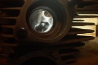
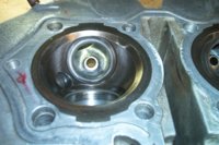
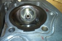
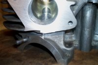
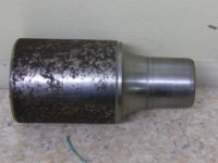
pics are of right side IN and EX valves from inside and outside, all inverted.
 

Attachments

  • IM004452.jpg
    IM004452.jpg
    152.1 KB · Views: 985
  • IM004453.jpg
    IM004453.jpg
    234.5 KB · Views: 1,409
  • IM004455.jpg
    IM004455.jpg
    195.3 KB · Views: 1,182
  • IM004457.jpg
    IM004457.jpg
    211.8 KB · Views: 1,244
bead blasting the intakes is not a bad idea. so far i just leave rough machining marks perpendicular to flow to, i think, keep the boundary layer from adhering.

the EX side will accumulate a few thou of carbon pretty quickly so i don't sweat that too much. the low angle light and flash pics make surfaces look rougher than they are...

any opinion on adding a fairing behind the intake guide? does anyone do that?
 
Nice work. True, the ex ports instantly start accumulating carbon, but a less friction, highly polished surface negates adhesion that much more....

one other concept that crossed my mind while making aluminum dust is that the cavity behind the intake valve guide could be dramatically streamlined if a built up shaped feature was "glued" in. velocity would likely increase but perhaps the turbulence in the intake pocket is more desirable?

The only material that expands and contracts like aluminum is, well, aluminum. I don't like gluing anything into an intake port that may have different thermal properties than the parent material. IMHO an aluminum welder could be used to build up a deflector that can then be blended to aid in shrouding the guide.

I'd be paranoid one could break apart. For the good ole XS, unnecessary. :twocents:
 
barncat,
It seems you are putting a lot of effort into the Dremel work, so I am a little surprised when I read this: "valves were cleaned up and lapped in thoroughly"
If this means a lot of lapping, this is rather counterproductive, as you most likely will end up with a valve and seat that neither flows nor seals as good as it could.
Traditional valve lapping should be kept to a minimum, instead the seats should be cut using a Serdi or equivalent machine, or with a hand held valve seat cutter. The norm is a 3-angle job (30-45-60 degree) and the 45 is the actual sealing surface, which needs to have a certain width maybe 2 mm on an XS intake (my guess) Then the valve needs to be re-surfaced in a valve grinder, either just to 46 degrees, or 3 angles as well (to improve flow) the 45/46 degree surfaces need to match, i.e have same diameters and widths. Slight lapping with a fine lapping paste is OK as a finishing touch, but extended lapping will again ruin the valve and seat.
Here is a good website: http://cylinderheadshop.com/
 
NONclow- i suppose i could put a finer finish on the EX ports, but they are smoother than they look as mentioned. i cut 1" discs out of used maroon Scotch Brite material and skewer them on a Dremel mandrel for smoothing and "polishing".

i agree with you that welding up and shaping fairings to shroud the back of the intake guides would be the only safe approach. epoxy would be iffy. it was more a thought experiment and query as to whether anyone has done that?? not sure whether it would improve performance or detract by reducing fuel/air atomization. probably overkill on an XS- just a general discussion topic...

arcticXS- fear not, the valves and seats are still in spec. just needed to remove some light pitting from the seats- i got a good consistent matte finish on all surfaces without overdoing it. i'll check for leaks when i reassemble the valves. the next step was to bite the bullet and buy a Mike's hand cutting set.

still looking for opinions yea or nea re JBweld on intake floors. was thinking cut some very light slots perpendicular to flow with a Dremel disc to lock the epoxy down. the temp rating is plenty high.

one other porting topic that comes to mind is the very pronounced factory step to a larger OD inside the exhaust ports. did Yamaha intend that to be an anti-reversion function? or is it just cheaper/easier machining?

on my first build i extended the custom header in to mate perfectly with that step to create a smooth 1 3/8" ID path out. on the second build i didn't bother and left that expansion to feed the 1 1/2" OD mandrel bend header. didn't seem to be any noticeable performance difference. (both exhaust systems have race type cans)
 
barncat,
I do not in any way claim much experience or expertise in cylinder head work, I just have the impression that the valve seat and port section next to it is more critical to good HP than the rest of the ports, since the valve and seat is the main flow "restriction" at the beginning and end of the valve events. So a lot can be lost or gained right there

Regarding the exhaust port step. MMM (650 Central) has inserts that fit with 1 1/2" OD headers (1 3/8" or 35 mm ID) The concensus seems to be that the step needs to be filled for best performance.

On the head I am working on, I machined some 35 mm ID alloy sleeves that are a light press fit in the head, these extend about 0,5 mm less than a new exhaust gasket. So when tightening the flange, the gasket gets good pressure, before the header flange touches the alloy sleeve. After mounting the sleeves in the head, there was still a minor step between port and sleeve, so I blended this transition using a sanding drum on the Dremel. So there will be a smooth port all the way from the valve into the header.

In general fluid mechanics theory, any abrupt change in cross section area will cause a resistance to flow, so should be avoided. Also, pressure waves (not to be confused with flowing gas) will also be reflected by cross sectional changers. I do doubt this is beneficial for performance.
 
Last edited:
IMO it's a compromise. An improvement intended for higher flow more apparent in the higher revs is great. How much power can these make @9k? Profiling and shrouding will have benefits, but I think they would be as negligible as the different exhausts.

I believe the "step" in the ex port is a profile machined/bored into the port to match the built-in-a-fixture, jig manufactured, factory double wall exhaust pipes. Speeding up production. I don't know of any aftermarket exhaust builders offering double wall pipes. Too expensive. As long as the outside o' the pipe matches the inside of the head, in the factory location, and has a larger inner dia., it's up to the customer to deal with the less than optimized flow. One just has to invest in the process of adequate porting (again, nice work), or a set of "torque optimizers".

Just depends on the set of pipes you're gonna run. :thumbsup:
 
arctic- yes, some guys spend a lot of $$ and time on valve work, but so long as the stock valves are clean, in spec, and seal properly that's good enough for me. i do not claim to be an expert on that, or porting either for that matter, but i enjoy porting work and it's free power. i just use a common sense approach to optimizing motors without a big investment. it's a nominal "50hp" motor... i say buy a crotch rocket if you want hi performance. i've owned several. kinda like the vintage bikes better.

your press in blended aluminum EX insert is a good idea. would be easier than extending the header in to match.

NONclow- continuing with the EX port step issue, i think i'll use arctic's solution then this time. though like i said, i did not notice any significant performance difference between my two previous header/exhaust system approaches.
 
Last edited:
i say buy a crotch rocket if you want hi performance. i've owned several. kinda like the vintage bikes better.

Ditto! They each have their places.....in my garage.:wink2:

Regarding the exhaust port step. MMM (650 Central) has inserts that fit with 1 1/2" OD headers (1 3/8" or 35 mm ID) The concensus seems to be that the step needs to be filled for best performance.

On the head I am working on, I machined some 35 mm ID alloy sleeves that are a light press fit in the head, these extend about 0,5 mm less than a new exhaust gasket. So when tightening the flange, the gasket gets good pressure, before the header flange touches the alloy sleeve. After mounting the sleeves in the head, there was still a minor step between port and sleeve, so I blended this transition using a sanding drum on the Dremel. So there will be a smooth port all the way from the valve into the header.

your press in blended aluminum EX insert is a good idea. would be easier than extending the header in to match.

NONclow- continuing with the EX port step issue, i think i'll use arctic's solution then this time. though like i said, i did not notice any significant performance difference between my two previous header/exhaust system approaches.

One and the same idea. Just a fancy term for the explanation arctic gave. :thumbsup: Don't get me wrong though, I prefer the hand built method too!
 
Filling that step in the port if using a stock style headpipe is difficult, if not impossible. The end of a stock headpipe inserts into that step but by how much will depend on how much you tighten it and how much the seal ring compresses. The width of the filler ring needed would change (get smaller) as the seal ring got compressed more and more. Yamaha made the step lots deeper than needed. Even if you insert a stock headpipe in there with no seal ring, there's still nearly 1/4" of the step showing. That giant "trench" in the port has got to be detrimental to the flow.

I have aftermarket MAC headpipes that just have the common rolled flange and lip on the end for sealing. They don't stick into the port like a stock pipe does. The problem with my pipes was that lip was very small, too small to seal right on the seal ring. They leaked like crazy. I fixed them by using the ends of old stock headpipes as an insert. This centered the pipe on the seal ring and in the port. They mount rock solid now and seal up great .....

HomemadeARs.jpg


Since my insert goes directly into the port with no seal ring, I was able to make a pipe ring filler for the remaining exposed portion of that step .....

FillerRing.jpg


The whole "stack" goes into the head like so .....

Inserts.jpg


Although my intent was just a better pipe mount, I later realized I had made my own AR inserts. "D" porting them shouldn't be too difficult and I may try that on the next set I make up. After the above "fix", I found the bike to be much freer revving. I can't say if that was the result of just properly sealing the pipe mounts or the addition of the "homemade" AR inserts. Maybe it was a bit of both.
 
Signal- lot of info in your link. thanks. D-shaped intake ports get mentioned quite a bit but i've not heard of D exhaust much. seems like that would be hard to blend in the port as an insert. would you care to elaborate as to performance advantages and port matching with headers etc...? is that supposed to be used with the bell shaped anti-reversion?
 
5twins- your post showed up just after i posted mine... looks like your setup works well. it is important to get a good seal at the head/ header junction of course. i made a fairly involved setup back in my thread "custom EPO's mild porting". there is no easy way to deal with that step in the EX port, and it's also hard to recycle the triple wall stock header flanges to mate them to 1 1/2" OD mandrel bend pipes.
 
I had to cut through and peel off the outer headpipe layer, then do a little grinding and filing, to get the "inserts" to fit into my 1.5" MACs. If I had access to a lathe, I would like to thin that thick flange down. If done from the inside, you might be able to get it inserted into the head enough to fill that step without the need for a filler ring. The flange wouldn't need to be left very thick, probably not much more than 1/16" or 3/32". It's not supporting the mounting flange or compressing the seal ring anymore, it's just trapped in place between the port and pipe.
 
i've never seen an SR500. i assume they have the same step in the EX port then? no dyno access here...

common sense would suggest that a consistent EX port OD matched to whatever header ID you're using would be the best setup, but that's just a guess.
 
Well barncat you caused me to do a bit of work to find some written details of the advantages of D shaped exhaust porting in motorcycles.

Page 73 of Sportbike Performance Handbook by Kevin Cameron has an explanation. I found it on google books (can't figure out how to hyperlink it).

I have no proof that it is advantageous in an XS, or that filling in the exhaust flange ring with a D shaped insert is sufficient. I suspect it would help and it could be removed if found to be detrimental.

On one XS I have that has been ported it has aluminium D shaped inserts in the exhaust. The insert is held in place by a countersunk screw threaded into the insert from the underside of the head. I did have some photos but have lost them. Will take some next time I have the exhaust off.

This bike also runs reducers in the end of the 1 ¾ inch exhaust pipe. Attached is a photo of the mandrel used to shape the exhaust pipe reducers.
 

Attachments

  • DSCF0323 (800x600).jpg
    DSCF0323 (800x600).jpg
    218.4 KB · Views: 395
Signal- i'll see whether i can find the Cameron material. i'm curious as to what the whole D-shape phenomenon is about anyway. most obvious guess is it forces/compresses gas flow toward the port roof. do you have any A/B "seat of the pants" dyno observations of your bike's performance with and without the D-EX mods?

also, by "end" of the exhaust pipe i assume you mean the head end. that just seems counterintuitive to me- almost like just using the heavy restrictive stock headers, but what do i know... you are talking large displacement race motor... mine will just be another carbed, free breathing street setup.

as mentioned in my original post, i'm going to eventually build a single carb intake manifold for this motor to see how that feels. same skill set as building headers. you'd think power delivery would be super smooth when properly tuned, but this is veering off topic.
 
Good reading here:

http://xs650forum.proboards.com/thread/1396

In the 5th post:

"A port, no matter how bent, should flow like it is straight. The straighter the port the better the flow. How do you get a port with a bend in it to flow like it is straight? If one looks at a bent pipe from the side (mind experiment) you see the air has longer to go around the top than the bottom of the bend. this differnce in distance leads to the air shearing and turbulance. If the bottom were gradually widened to the middle of the bend the air would slow on the bottom and match the speed on the top. As the widened bottom would taper back after the bend, the air on the bottom would match the speed of the air on top and the port would flow no different than a straight pipe. This concept uses the elasticity of air."
 
that explanation is pretty unclear, and basically wrong as i understand it.

gases have a longer path to travel along an XS port roof and therefore are moving faster than along the port floor. building up the floor creates a Venturi (sped up) effect by reducing cross sectional area and allows for forming a somewhat less abrupt radius on the short turn, thereby improving overall flow characteristics. in my layman's terms...

that still doesn't address why a pronounced D shape is better than what would in effect be a blended C with a flat bottom.

gotta do some more reading, but this head is pretty much done for my purposes. need to dust off a spot or two next to the EX guides. the more you look at your work minor imperfections become obvious...
 
Last edited:
Back
Top