YL82
Perpetual Restorationist
Deleted. I had ordered a wiring harness from Lowbrow Customs, but it turned out to be the female ends, which I did not need.
Last edited:
")
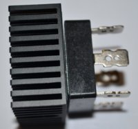
I will likely use the wiring/3-pin connector from my regulator when I get my VR-115. Not sure that I want to use the connector and wiring from my rectifier, but will if I don't have a better choice. I've been looking on the internet for quite a while for replacement connectors.
Will Yamaha-type 6-pin and 3-pin connectors (male) be difficult to find on the internet if I wish to replace connectors with new?
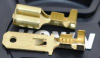
Is there a good internet source for replacement large, flate spade-type connectors, both male and female that are compatible with these Yamaha connectors?
Thanks!
650Skull,
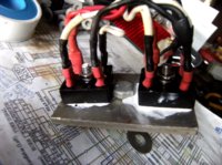
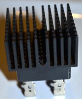
I assume you used a silicone-based heat sink compound on your rectifier? Thanks.
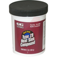
I plan to use Type Z9 (silicone/zinc) Heat Sink Compound from GC Electronics.
I'm using mostly original stuff from old harnesses. I think it's 18ga.
Somewhere on his web site, he let on that his $15 terminal removal tool was from Lisle. I found it cheaper on Amazon so ordered it there .....
http://www.amazon.com/Lisle-14900-Wire-Terminal-Trouble/dp/B0002STTQG/ref=pd_bxgy_hi_text_z
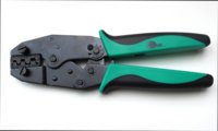
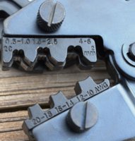
on how to properly orient/load the 6.3 mm (.250) spade terminals into a crimper. I know its a 2-step process using the crimper, first the conductor (wire) and then the insulator. I'll practice all day long and have butchered a number of terminals, but I really need to first know how to load them into the crimper.