-
Enjoy XS650.com? Consider making a donation to help support the site.
XS650.com receives a small share of sales from some links on this page, but direct donations have a much greater impact on keeping this site going.
You are using an out of date browser. It may not display this or other websites correctly.
You should upgrade or use an alternative browser.
You should upgrade or use an alternative browser.
Rotor Winding Tooling
- Thread starter Jim
- Start date
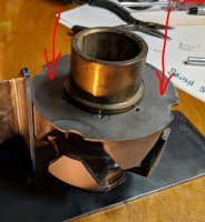
.... The rotor above failed the runout test... to the tune of .015-.020" at the outer ring.
Is the phenolic plate of uniform thickness?
It is. Just for s&g's I checked the rotor with and without the ring plate. Same reading. It's 15 to 20 thou.... you can literally see it with the MK.I eyeball... no TIR gauge needed. It's that bad.Is the phenolic plate of uniform thickness?
I came up with a fix. Smeared JB Weld on the face and turned it down flat. For reasons too numerous to go into (mostly thickness and balance), I didn't want to turn the rotor itself. Not sure I trust it. Shelved it for now....
Nice fix.
Now you got me curious.
I wonder if it would show similar runout if position measurements were taken from each of the 4 prong endfaces?

Now you got me curious.
I wonder if it would show similar runout if position measurements were taken from each of the 4 prong endfaces?
I'm sure it would. I didn't take a pic but before I put the JB Weld on it, I put a straight edge across it. It's definitely bent.I wonder if it would show similar runout if position measurements were taken from each of the 4 prong endfaces?
Curious about your reassembly press fixturing/procedure.

Thinkin' out loud here.
There's 3 types of alignment during press-assembly.
- Self-aligning, let the top align with the bottom's shaft body.
- Parallel plane, the upper press plate is parallel with the bottom press plate.
- CoAxial, the upper press plate is perpendicular to the tapered shaft axis.

Thinkin' out loud here.
There's 3 types of alignment during press-assembly.
- Self-aligning, let the top align with the bottom's shaft body.
- Parallel plane, the upper press plate is parallel with the bottom press plate.
- CoAxial, the upper press plate is perpendicular to the tapered shaft axis.
- Parallel plane, the upper press plate is parallel with the bottom press plate.Curious about your reassembly press fixturing/procedure.
View attachment 135920
Thinkin' out loud here.
There's 3 types of alignment during press-assembly.
- Self-aligning, let the top align with the bottom's shaft body.
- Parallel plane, the upper press plate is parallel with the bottom press plate.
- CoAxial, the upper press plate is perpendicular to the tapered shaft axis.
There's a half inch steel plate that sits on top of the brass bushing. Parallel to the bottom bushing face.
Wish I was there. I love these kinds of challenges...
You're welcome here anytime Steve. 
Barring any new snakes popping their ugly heads up.... I think I finally got it. Press fixtures work great. Ya just gotta have two halves that aren't bent to start with... ....
....
Barring any new snakes popping their ugly heads up.... I think I finally got it. Press fixtures work great. Ya just gotta have two halves that aren't bent to start with...

I can't think of any downfalls to your epoxy-faced rotor, aside from balance. JB-weld temp rating at least 500°F, strength on par with the phenolic disc. The benefit would be having true-running sliprings, an enhancement feature to your rebuilds.
I think there would be a volunteer in here to try it.
Edit: Just thought of one.
The rotor OD may need to be shaved if the runout affects it...
I think there would be a volunteer in here to try it.
Edit: Just thought of one.
The rotor OD may need to be shaved if the runout affects it...
Ooooh... good point. You have any idea what the typical clearance is 'tween the rotor and stator?Edit: Just thought of one.
The rotor OD may need to be shaved if the runout affects it...
Sorry, no. Probably have to get the Barabooian to get you some ID/OD measurements...
Ah but finding gotchas during beta testing, tooling up phase, Priceless!
Good catch.
Good catch.

Off the cuff, On assembly if the stator slot isn't aligned with the crank location pin the stator is cocked enough to make the rotor rub (HARD)
Re, usable cores and non-usable cores. Without altering the parts, were there any usable parts on that rotor that could be matched with other rotor parts? I'm thinking about a shop that I know has saved every bad rotor that they've ever had with the idea of finding someone someday to rewind them. Wonder how many of those cores are not usable. Wonder what damage he's done throwing them in the boxes.
Scott
Scott
Yeah there is. Might just use it for parts.were there any usable parts on that rotor that could be matched with other rotor parts?
I don't have calipers with deep enough jaws, so I set a rotor inside a stator and could not get a piece of .032" safety wire between 'em. So I stuffed a tooth pick 'tween em and measured the crush. Gap is .028". So.... 14 thou. wobble would rub. That ain't much folks.Off the cuff, On assembly if the stator slot isn't aligned with the crank location pin the stator is cocked enough to make the rotor rub (HARD)
Similar threads
- Replies
- 35
- Views
- 5K


