Safety Relay Circuitry

Crb999

Christopher Bruce*OSS 大名
Messages
28
Reaction score
5
Points
1
Location
Oban, Scotland
14680118778821012520316.jpg
Hi all,

In the process of trying to make sense of the Safety Relay and the Reserve Lighting Unit, I felt the need to draw up the circuit for myself.

This does not claim to be the actual circuit inside the unit but if it was needed, then this circuit would accomplish the same functions.
 

Attachments

  • 20160708_212718.jpg
    20160708_212718.jpg
    45.5 KB · Views: 296
Mmmmmm! Didn't quite come out as expected:

Here is the explanation

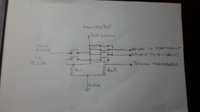
The schematic shows the start condition just after switching the ignition on.
The following condition are true:

1/ Via RL2, 12V is available to the Red/Yellow ignition circuit
2/ Via RL2, 12V is available to the other Red/Yellow for the starter circuit
3/ There is no 12V to the RLU

Start the engine:

4/ The Yellow from the alternator now provides power which operates RL2.
5/ RL2 now opens the contacts removing the 12V from the start circuit (other Red/Yellow).
6/ There is a momentary interruption of the supply to ignition as the contacts change.
7/ RL1 receives 12V from RL2 and changes state.
8/ RL1 now provides 12V to itself and it is now locked on until the ignition is switched off.
9/ RL1 now supplies 12V to the RLU via the Blue/Black wire enabling the headlights.
10/ This state continues irrespective of the engine until the ignition is turned off.

It would be possible to continue the isolation of the start circuit via extra Normally Closed contacts on RL1 but that would require the ignition to be turned off then on again to avoid the 'starter plus headlight' problem, but in a stall situation, speed is essential!
 
I'm not going to be much help here, since I'm unfamiliar with the later models, but I seem to recall that it was pointed out by the senior members here (Retiredgentleman, 5twins, ...etc.) that the manual's schematic diagram for the safety relay was drawn in error, and the folks here long ago came up with a revision of that schematic.

Here's the manual's version in error:

80s-Safety-Bad.jpg


Here's the revised schematic the gurus produced:

80s-Safety.jpg


Unfortunately, I don't know where the discussion threads are that covered this...
 
That's a useful correction but it doesn't explain the function of the "Safety Relay" or how the lights fit into the picture.
 
mmmmmm....... well that told you 2many !:poke::lmao:

Thanks for posting both of you . I'll take a timeout this morning and go through the diagrams . Its one of the many aspects of the electrickery system I haven't yet got clear in my head.
I'll have to shove something out to make some space.;)
 
Sorry i sounded curt! It was the safety relay itself that concerned me and hw it stopped the lights from working.

In the UK we don't have to have the headlights on during the day so we are used to an On/Off switch for the lights and then a High/Low switch.

There is no reason to have all this intelock for the lights that the safety relay provides as we wouldn't normally switch the lights on before the engine was started and it follows that we can decide whether the lights will be on or off if the engine stops!

So, on my newly acquired bike, the headlight didn't work! The circuit I provided above was my attempt to find out why the lights didn't work.

I couldn't run the engine, but that would have made it easier to understand.

In the circuit from 2many... The safety relay is shown with just one set of contacts and no means of actuation but my suggested circuit shows the likely set up and its relationship with the lights.

I've ditched the RLU altogether. I do run with the headlights on during the day, I'll be fitting led driving lights too but at night if a filment fails I'll know it!
 
I was just kiddin Christopher ...its my Cockney sense of humour I'm afraid.

I think your idea is an excellent one and I for one welcome it. Most folk are happy to just open the fridge door and take out a cold beer , wheras I am cursed with having to understand exactly how the fridge works ...:geek:

The operation of the safety relay is one of those electrical components that make everyone groan ... I'm looking forward to seeing your final schematic with explanation and guide to bypassing it .
 
Er... Is that your cockney humour again? :)

I like the function of the safety relay and I also like the headlights being off until the engine is running so I dont want to bypass it in any way.

All these additional safeguards like side stand switch, neutral swich, colour of socks switch, clutch switch etc become a real problem when they go wrong 'costhe bike won't run but when they are working we don't even think about them.

My circuit, posted at 10:06 followed by explanation at 10:12 may well be final editions unless I've got it wrong! I've been known to get it wrong :)

I didn't bother to add in all the other little safeguards because their action is fairly obvious.

If my explanation is a bit foggy for anybody, I could explain it in less technical terms. No extra charge.

Later :)
 
QUOTE
In the UK we don't have to have the headlights on during the day so we are used to an On/Off switch for the lights and then a High/Low switch.

There is no reason to have all this intelock for the lights that the safety relay provides as we wouldn't normally switch the lights on before the engine was started and it follows that we can decide whether the lights will be on or off if the engine stops!


I took this to mean that you wanted to do away with the safety relay and have an on/off switch ......:wtf:
Why would you want both operable ? no on second thoughts please don't explain..:doh:
 
:) I'll tell you this, only once , the safety relay is about preventing the starter operating when the engine is running. The lights side of it was an afterthought.

Beer!
 
Crb999;

Your sketch of the 1980 to 1984 Safety Relay was a very good attempt, but I think there are some errors in it. I've quickly sketched up what I believe is more accurate. My sketch may not be 100% accurate either. For example, since the yellow wire has AC voltage from the alternator, there may be a diode in the SR circuit, or the SR may be constructed to deal with the AC ??? Also around the 1980 year, the SR appears to have changed from 1 relay to 2 relays, but I think it still functions the same as 1 relay.
Safety Relay 1980 to 1984.JPG


Edit:
I see you live in Oban, Scotland. About 7 weeks ago I was travelling very close to Oban. I went to the Inveraray Castle in Inveraray. I am of Scottish descent as my last name is Campbell, and a visit to the ancestral home of the Campbell clan was very enjoyable to say the least. You live in a beautiful country.....................the highlands are very rugged!
 
Last edited:
Hello retiredgentleman, I'm a Bruce so our links go a long way back :) You are right, this is a beautiful part of the world. I also have the status of your nomdeplume, so I have plenty of time to enjoy it. I live on Loch Awe, about an hour from Inverrary.

Yes, I like it. Your circuit is more elegant than mine but a couple of errors that I suspect are that you would need a blocking diode to protect the alternator once the relay operated whether the output from the alternator was ac or dc and more importantly, if the engine stalled, you would not be able to restart without turning the ignition off first.

Now that might be the case! I've never had this lot working so it is conjecture on my part :)

Do you have to turn the ignition off and then back on again to restart? I worked on the premise that you wouldn't have to do that but it's just a guess.

Well get it in the end :)

Regards
 
Quote;
"if the engine stalled, you would not be able to restart without turning the ignition off first. "
I believe that is exactly how it works with the 1980 to 1984 models.
 
Excellent. That clears that up then. Just got to resove the ac/dc problem on the relay.

The only advantage my circuit has is that with 2 relays there is no conflict.

In your circuit, a second relay, normally open and powered by the alternator could supply 12V to the relay you've drawn at the point the alternator feeds it now.
 
Back
Top