Simple Wiring Using Stock Switches and Lights

PHeller

Erie, PA
Messages
410
Reaction score
1
Points
16
Location
Erie, PA
I've got PMA and will soon have a PAMCO.

I will be removing the key switch in favor of a hidden toggle.

Hand switch (signals, horn, three-way, lights, etc) will remain stock.

First: Anyone have a colorful wiring diagram with this setup?

Second: What is the process/plan for removing all the wiring in the headlight bucket? Is there a better place to locate the quick disconnects for gauge wiring, hand switch, and headlights?
 
I've been looking/redoing a wiring diagram from a 78SE (I've got a 78 Standard).

I've figured out much if it, but the switch gear has me boggled. Where does the power for turn signal switch come in from? Yellow/Red?

It appears Brown/White goes to the flasher and Green and Brown go to the signals. But the Yellow/Red wire has me stumped.
 
On my 75 when I rewired it I pulled all the plug ins out of the headlight, removed the connectors and hard wired them into the harness under the tank.
On the turn signals power to the switch is the brown/white wire.
The turn signal circuit is pretty straight forward. Power comes from after the main switch on the brown wire. The brown wire feeds the flasher, from the flasher on the brown/white wire to the switch, from the switch on the dark green and chocolate wires to the signals.
The yellow/red wire goes to the self canceler. Ignore it.
Leo
 
Leo, always the XS650 scholar.

While I'm at it, what's the main power wire color for the headlight switch? It looks like yellow/black.

I'm basically bypassing the light checker, saftey relay, signal canceller, and reserve lighting unit, but it appears like all the components that are controlled by these units have two power wires.

The headlight hi/lo switch is one of them. I see a yellow/black, L/Y and L/G with Green and Yellow going out to the light. So which was is the power in?

I plan to feed all the control "power in" wires with the "Lights On/Off" feed, so I can still turn all my lights off.
 
On my bobber I used a set of MikesXS Chrome controls that are like the Stock ones. I also built my own wire harness. I ended up tucking everything under the tank.

Essentially what I did is get out my $5 HF multimeter and started testing and labeling wires.
 
On the 78's power goes into the headlight switch on the red/yellow wire and out on the blue. The blue/black comes from the safety relay to turn the lights on when the engine starts. In a simplified harness you can ignore this wire.
Run the blue wire to the tail light and the dimmer switch blue/yellow wire. From the dimmer switch the yellow to high beam, the green to low beam of the headlight.
The other two wires L/G and Y/B go to the reserve lighting unit. When one headlight beam blows out the RLU lights the other beam at half power so you know the bulb is blown and lets you get home. It uses the L/G and Y/B to do this.
You can ignore these wires too.
Leo
 
On the 78's power goes into the headlight switch on the red/yellow wire and out on the blue.
Out on the blue to where? The tail light?
Run the blue wire to the tail light and the dimmer switch blue/yellow wire.
The blue wire to the tail light and to dimmer switch? Is what your calling the dimmer switch the "Lights On/Off" or Hi/Lo Beam?
From the dimmer switch the yellow to high beam, the green to low beam of the headlight.
Leo

Just want to clarify the "Dimmer".

I'm wondering the simplest order for keeping the "Lights On/Off" in working order.

Would I just have the power go from Lights On/Off switch to the red/yellow wire?

Posted via Mobile
 
When I say headlight switch I mean the on/off switch. The dimmer switch is the hi/lo beam switch.
Power comes IN to the headlight on/off switch on the red/yellow wire. Power comes out on the blue wire.
This power out on the blue wire you run to the tail light and the blue/yellow wire on the dimmer or hi/lo beam switch.
I like this diagram. It is in color and it shows the basic points ignition wiring. It also has boxes with the TCI and the Combo reg/rec that you just swap around to match what you have.
Leo
 

Attachments

  • 314w9s3.jpg
    314w9s3.jpg
    135.4 KB · Views: 639
I think I'm getting it. I've resorted to using MS Paint as a quick means of editing the wiring diragrams for my use.

However, I can't seem to figure out how the brake light indicator is wired.
 
The brake light indicater lights up if the brake light blows. The light checker Is wired off the yellow wire that runs from the brake light switches to the brake light. I'm not sure how it does it but the light checker sences the current draw of the brake light and if no current draw as in a blown bulb it grounds the green/white wire and lights the brake light indicater on the dash. Lighting the indicater tells you if the brake light isn't working.
The indicator light gets power on the brown wire that powers most of the bike, things like the horn, turn signals, brake light, and a few other things. The green/white wire from the indicator gets grounded by the light checker to turn it on.
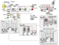
If you are using the stock alternator I might hook in a lighting relay to light that indicater as a charge indicater light.
To hook it up, hook a wire from the yellow wire on the stock alternator to terminal 85 on the relay, ground terminal 86.
The green/white wire from the light checker plug in to terminal 30, terminal 87A to ground.
This way when you turn on the key the light on the dash lights up, indicating the alternator isn't making power. When you start the bike power is sent out on the yellow wire. This power trips the relay. The relay breaks the connnection from 30 to 87A and the indicator on the dash goes out. Works light the idiot light on a car.
I think 5twins or Pamcopete does a simular mod to use the white headlight indicator light as a charge indicator light. I think a red light will be more noticable. We have been trained that red means danger and to always notice red things. Traffic lights, brake lights and lights on cop cars are examples.
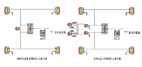
You can get the relay at most any parts store, some are only used to turn something on. These have just four terminals. This mod needs one with the fifth terminal, to turn something off. These cost a bit more. The four terminals might cost around $5, the Five terminal may cost around $10.
Not quite as easy to install as a volt meter but look more like stock.
A volt meter or this type of mod will tell you if the alternator quits and lets you get home or a lot closer before the battery goes dead.
If you have done the PMA this mod won't work. Same reason the safety relay won't work, no yellow wire on the PMA mod.
Leo
 
I'm running the PMA.

My hope is that i'll be able to draft up a wiring diagram for folks who did the same as me. Everything stock except starter-delete, PMA and PAMCO. LED lights as well.

Posted via Mobile
 
Here is the current state of my wiring diagram.

It does not show stock wiring colors (yellow in brake system is actually green/yellow) and it doesn't show the grounding harness.

That where my questions still are...I've got to figure out which components needs grounding, and where the easiest/shortest/best ground spot is for those components.
 

Attachments

  • WiringDiagramRunPlan.JPG
    WiringDiagramRunPlan.JPG
    77.8 KB · Views: 691
In your diagram you have one indicator light for the turn signals. This works with the stock bulbs but won't work with LED's. In the srtock set up it worked ok because the two 27 watt bulbs draw a lot more current than the indicator bulb.
With LED's they draw hardley any current. The indicator will feed power to both sides of the turnsignals. It might be better to wire in two LED's in the placewhere the stock indicator is, hot from each side to hot of the LED's, ground the other leads.
On your brake indicator light you have the brown wire to the harness brown wire. The yellow to after the brake switch. This way when you turn on the key power is sent to the indicator light, then to the brake light. This may make the indicator and brake light be on all the time, not full bright but maybe about 1/2 bright. Then when you use thebrake power will flow on the yellow wire, making the brake light come on and still leave the indicator on 1/2 bright.
On your turn signals, do they mount right to the frame? Most ground through the body of the signal. The mount bolt/nut that hold it on also provide the ground. Just be sure you have a clean metal to metal connection at each signal or run a wire from under the mount nut to a good frame ground or right back to where you hook the battery to ground. I would try the frame as ground first, if it won't work well then add the wire to battery ground.
The headlight ground should be run out of the headlight bucket to a frame ground.
The Horn button grounds through the black wire that ran from the left switch housing down into the headlight bucket and plugged into the harness ground. This I would move under the tank and hook it under one of the coil mount bolts. A clean metal to metal connection here as well.
The Pamco need a ground. It can go under the coil mount bolt with the horn button. This would be a good place to ground the headlight as well.
So a run down is headlight, horn and Pamco grounded under a coil mount bolt.
Turns frame.
Oh almost forgot the tail light. The body is the ground. If your fender has a solid metal to metal mount, with a clean metal to metal connection then that should be ground enough. If it has the stock type rubber mounting then run a ground wire from thr bdy of the tail light, under a mount bolt is good, to a good frame mount. Where the signals mount or to the battery ground.
Ok just a bit of clarification on things. When I say battery ground you don't hook the wires straight to the battery. Most batteries have a heavy wire from the negitive terminal to the frame some where. Often very close to the battery. In the stock bikes the battery ground hooked under a bolt in the frame just behind the battery. This will help keep corrosion out of the ground wires. Hooked right to the battery promotes corrosion.
Any place you hook a wire to the frame you need to clean of any paint or powder coat. so you have a direct metal to metal connection.
A dab of grease helps keep these connections free of corrosion.
Hope this helps.
Leo
 
In your diagram you have one indicator light for the turn signals. This works with the stock bulbs but won't work with LED's. In the srtock set up it worked ok because the two 27 watt bulbs draw a lot more current than the indicator bulb.
With LED's they draw hardley any current. The indicator will feed power to both sides of the turnsignals. It might be better to wire in two LED's in the placewhere the stock indicator is, hot from each side to hot of the LED's, ground the other leads.

What if the indicator is LED as well? I'm looking at a speedometer with built in indicators.

On your brake indicator light you have the brown wire to the harness brown wire. The yellow to after the brake switch. This way when you turn on the key power is sent to the indicator light, then to the brake light. This may make the indicator and brake light be on all the time, not full bright but maybe about 1/2 bright. Then when you use thebrake power will flow on the yellow wire, making the brake light come on and still leave the indicator on 1/2 bright.

So I want the indicator to be hooked to the yellow wire?

Posted via Mobile
 
the way your diagram is now your indicator and brake light are running in series they will be on all the time, disconnect the brown from the indicator and hook it to ground instead then indicator will light when brake is on, on the turn signals there are two ways to do indicators the single bulb method requires a regular bulb since voltage/current will flow either way thru it, a LED will only flow one direction so you will need two led bulbs they can be wired in one facing one v/c direction and one the other then placed into the same lamp socket, tricking it into a dual lamp configuration.... your neutral switch one side needs to go to brown for power the light blue is a grounding wire (completes circuit)


1000 posts woohoo:laugh:
 

Attachments

  • turn signal wiring.PNG
    turn signal wiring.PNG
    13.5 KB · Views: 295
  • WiringDiagramRunPlan.jpg
    WiringDiagramRunPlan.jpg
    68.6 KB · Views: 401
Last edited:
The brake indicator light was to tell if the brake light bulb was blown. To have it light when you use the brake won't serve any purpose. Even when the brake light bulb blows the indicator will still light up. THe only way to get it to work as a failure light is to use the light checker. Myself, I wouldn't use it as a brake indicater light. I would wire as an alternator charge light.
Jayel, I don't think your first diagram will work with LED turn signals. Your second looks like it should. When you turn the signals on left power will go to the turns but also feed through the stock indicater light, and light the right side signals. The LED's won't draw enough current to get the indicater bulb to light.
On his neutral light he gets power from the lighting fuse. If you follow the dark blue off the neutral light it goes up and hooks into the blue wire that comes from the fuse to power the tail light and head light on/off switch. That should let the neutral light work ok.
Leo
 
Ok, I'm getting more of my parts installed, and relocating my key switch and a few other things.

So I'm ready to start wiring.

One thing I'm having trouble with is all the "loose" wires that will be clipped as a result of ditching the light checker, signal cancel, and safety relay.

So far I have identified the following:


Brown/White – From Flasher to Signal
Brown to Flasher
Dark Green to Signal
Dark Brown to Signal

Ignore Yellow/Red (Clip)
Blue/Green and Yellow/Black are reserve lighting unit (clip)
Blue/White from Right Side Starter Button (clip) not using starter
Red/White from Starter Solenoid to Key Switch (clip) not using starter

Red/Yellow – to Lights On/Off (Right Side)
Blue (from right side) to Blue/Yellow (Dimmer)
Blue (Left) – To Headlight low beam and Brake Light

Can someone help me identify the remaining factory wiring colors on a 1978 Standard? Many of the modified wiring diagrams don't show the factory colors, and the factory diagrams have so many colors its hard to tell which I'm keeping and which will be unnecessary.

Posted via Mobile
 
Last edited:
Hi, isn't the yellow/red wire for self cancelling, I think it goes to the 3 pin indicator relay, I dumped it, I use a 2 pin relay now
 
Correct, the yellow/red wire is used by the self canceler to stop the turns flashing. With the two prong flasher it won't be used.
Leo
 
Alright, not sure if this is an existing thread close enough to what I've got.

My 1978 E standard came to my hands after being shelved in wa state around 1994. I got it last year in ca and it had 9800 miles. Got it running with some fresh gas, new battery, and clean bs38 pair. All standard switches and components look intact. Been riding it the last few months and enjoying it.

Here comes the interesting part:

My oil pressure light comes on when I apply the brakes. Rolling or still, front or rear. Anybody know why?
 
Back
Top