So git 'er Done

After a quick spruce up of the worst muck from the carbs with some petrol I did a trial fitting.


IMG_2027.JPG


.. featuring the piece of wood from earlier to stop them sagging down.

IMG_2025.JPG

Looks like there's plenty of room now between the frame downpost and the modified bar.

(The yellow thing is a cable tie holding a bit of polythene over the fuel intake)
Note to self tidy up the wiring a bit. Yeuk.
 
IMG_2030.JPG

I've done a quick trial with throttle cables. If the outer is long enough the inner isn't.

Venhill and others do a universal kit for about £11. So I'll get one on order and cobble something together. The standard cable was useful to try out the ends fitting on the CVK. They are 6mm both ends and fit fine.
 
IMG_2032.JPG

There's some pretty ropey bits of electrical tape and some loose wires threatening shorts so I don't think in all good conscience I could ignore them. The air horns are wired with a piece of blue wire which is only JUST long enough and so takes a shortcut which is no-where near the frame.

I'd blame the PO but in this case I AM the PO. :)
 
Last edited:
Then you are just reaping what you sowed, lol.

I have both digital read-out and plain calipers. The digital read-out one is good for precise readings that need fractions of a MM in them. For most other "ball park" measuring, I just use a cheap plain plastic one, only a couple dollars at HF. And you're right, they are so handy, I use the thing constantly .....

tLOGe5L.jpg
 
Engineers are clever people.

You’re damned right we are Dave!

Stick at it mate - you’re making fine progress! You’ve really got a nice bike there. I’ve got to say - that is one serious muffler (silencer) on that 2->1 system. I’ve never seen one quite like that.

Pete
 
IMG_2047.JPG

I have tidied up that connector to the flasher relay which was about to fall off and checked the wiring diagram. Brown and white and Brown. It gave me a chance to practice reading a wiring diagram on something that I'm pretty sure was working.
 
IMG_2050.JPG

The mess of polythene and cellotape (my mess) in the previous pictures contained the two grey wires and the two orange wires. I guess these were from when I fitted the electronic ignition. I remember I wasn't too confident about my wiring abilities and so I probably left them so I could go back and never got around to doing the job properly. There were also a couple of black wires hanging nearby. I haven't a clue what they are so I'll cap the lot off and label them "start here" for when something isn't working sometime along the line.
 
Don't be intimidated by the seemingly complex wiring diagrams. They really aren't that hard to understand. Follow one pathway at a time from one end to the other, and its relationship to the others. Take your time, and before you know it, a lightbulb will appear above your head. You'll get it, and so will your bike. Best of luck to ya!
 
IMG_2048.JPG

IMG_2051.JPG

Fiddling with the badly routed / too short blue wire powering the air horn's compressor made this fall out. WTF? Panic.

But I see its a relay. A quick check of the wiring diagram showed that Brown and Pink wires originally went to the horn and now control the relay.

My understanding of a relay is that it is used where a device draws a more power than the other components. So it:
a. prevents a large current from going through the small horn switch on the handlebars.
b. allows a meatier wiring to be used to power in this case the horn

(there's also a handy diagram of a relay on the relay. LOL)

So this wiring does the first, but although the blue and the yellow wire are chunkier than the main wiring harness the yellow wire is just tapped into a brown harness wire, off the picture. (so it doesn't achieve the second) I'm guessing that I can just connect the pins that are currently wired brown and yellow. The horned worked in the past and there are no signs of burning wires. When I get to the stage of fitting a battery I'll find out what the current draw for the compressor is before I press the button.

The yellow wire was actually jammed into a female bullet joint and the male bullet jammed in afterwards. This caused a bit of head scratching when I found I had a bare yellow wire and a dangling bullet which didn't seem to want to stop where it logically had fallen from.

(I don't admit to this wiring. Not my handywork.)
 
Last edited:
IMG_2052.JPG

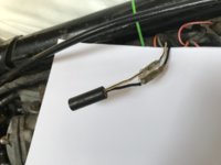
Anyone know what this is? The bike worked at one time so its not a problem. I'm just curious. I did think rectifier condenser (now defunct if it is). There are no rectifiers condensors on the back of the head steady brackets, which is where I though they were.
 

Attachments

  • IMG_2052.JPG
    IMG_2052.JPG
    81.5 KB · Views: 157
Last edited:
View attachment 123636
Anyone know what this is? The bike worked at one time so its not a problem. I'm just curious. I did think rectifier (now defunct if it is). There are no rectifiers on the back of the head steady brackets which is where I though they were.

HI Dave: That little black cylinder is a condensor and it is there to reduce arcing at the ignition points so that they last longer.

Keep going mate - you’ll get there!

Pete
 
IMG_2053.JPG


DOH - Yeah condenser, capacitor. Don't know why I said "rectifier". Anyway, 22 in this diagram, though the wire colours are different. So I guess its partner is somewhere about. I'll pop them in my "not needed on voyage" box and the wires can join my obsolete tail ends.
 
BSP049.jpg


After a quick look online some while ago I saw that single disk US versions have the disk on the right hand side. So, that that's where I fitted the better of two disks.

I bought this from Yambits https://yambits.co.uk/xs650-brake-caliper-p-38993.html?osCsid=m0772h9afmvq663ntfo6vsft70 and realised it was meant to fit on the left at the rear. My callipers were both at the rear. After a quick look more carefully online I realise that most singe disks are on the right at the front. Scratches head. Makes executive decision. Mine is going to be on the rear on the right. ("This is my xs650b. There are many like it … but this one is mine.")

The calliper can be "handed" by swapping the bolt and the stud. Easy.
But after a couple of hours of sweat trying to get either out I managed only to get the bolt out. But it was tight then loose all the way out. It took a while with Coppaslip working the thread backwards and forwards before I was happy. None of my sockets was deep enough to accommodate the stud and using a ring spanner only risked damaging the flatted bit of it.

There's a bloke up the lane with a Harley and he's always in his garage. He's the sort who has a long white beard and is never out of red overalls. So I trudged up the lane to share my problem with him. The stud thread was even tighter than the bolt to the point of casting doubt whether they could in fact be swapped over. The stud tightened up in the bolt hole and would go no further. Suffice it to say after some judicious measuring and some more Coppaslip and working of the threads we (he) ended up with a calliper that could be swapped either side with relative ease.

So thanks Harley guy. I'm popping along later with a bottle of red wine.

So far the caliper seems like a reasonable bit of kit. The original is not available so Yambits have had this remanufactured and I'm glad it exists. It comes with pads and the shims (the shims on their own are £15). It can be fitted with either the original metal brake line or apparently has been machine to accommodate a banjo.
 
Last edited:
Back
Top