some wiring diagrams

The rectifier gets warm it should NOT go in the box. The regulator has a green tube along one side. It gets warm. I don't think it should go in a box either.
I would upgrade the reg and rec to a more modern replacement. I used a $13 reg from a 75 Dodge Dart. A set of $7 Radio Shack Rectifiers A few minutes time to assemble and get great charging.
If you shop online you can get the parts checper. They have 3 phase rectifiers for around $3-$4. The regs run from around $9 and up.
On these the reg can go in the box but the rec should be out side. Bolted to the box is ok, it can be extra heat sink.
Leo
 
Thanks Leo,

1 more thing the ignition coils, Both my coils have orange and brown wires.

the brown wires go to the red and white wire that is fused and connects to the ignition. the orange goes to the "thing that is mounted under the top motor mount??? Attached to the motor mount is a small round...... looks likea coil mabie or big resistor, i dont know" it has 2 wire (black) and a ground mabie i should takes some pics later. thanks all
 
Heres a pic, under the bracket that bolts to the frame there ia coil like looking think, with 2 wires (black) and also a ground, do the orange wire on the coil hook into these? thanks
 

Attachments

  • first build.JPG
    first build.JPG
    62.2 KB · Views: 190
Yes, the thing on the top mount is actually two condensers. The wires are the hot, they hook to the same wires as the points. The body of the condenser is ground. The two are mounted end to end in one case that is inside the mount that attaches to the engine mount.
One coil wire goes to the red/white wire. This is power in. It doesn't really matter which color. The bike will run fine either way. You can try it both ways to see if it changes anything.
The other coil wire goes to the condensers and points.
Power goes to the coil, from the coil to the points and condenser. the points open and close to turn the power flow through the coil on/off. The condensers absorb some of this power as the points open to prevent arcing of the points.
When the points open is when the coils fire the plugs.
One more thing. The upper set of points control the right coil. The lower control the left. Make sure you points are wired to the proper coil.
Leo
 
Heres a pic, under the bracket that bolts to the frame there ia coil like looking think, with 2 wires (black) and also a ground, do the orange wire on the coil hook into these? thanks
that is the condensers they (one wire each) connect to the coils and the points.... like this pic
 

Attachments

  • untitled.PNG
    untitled.PNG
    5.7 KB · Views: 213
sorry to jump in but can't make my own thread yet...just bought an 80 xs650 and put a new battery in it, started up great after I got new plugs, even ran great around the block. Parked it, let it sit for a few days, started right up and went to autozone 4 blocks away for brake fluid. I was in there for 20 minutes and when I came out the bike wouldn't start! They charged it up, but when I connected the wires again the bike came on and I started it without the key in the ignition...I'm not sure what I did...but I've been reading a lot and electricity is kicking my arse :/
 
OK all, who has the " im an idiot and cant wire a bike for the life of me manual?"

So i have 78 650, and all im trying to do is get it wired to run and have a head light and brake light, I know it should be easy but not for me:banghead:

any thoughts, i have the wiring diagrams, i have done it twice to what i thought was right and nothing

anybody in norfolk va or elezebeth city nc

thanks
 
i dont really expect anyone making a diagram for a hard tail with just head light, brake light and coils. but i wanted to see if anyone has undertaken re wiring theirbike and could give me some advice
 
I am rewiring my whole bike right now and it's my first time. My advice would be take it slow and just go 1 wire at a time. Once you start running wires and connecting them, it all starts to come together. It's really not as bad as I thought it would be - the diagrams make them more intimidating than they are for a newbie and I speak from experience. I would say get a good set of wiring tools (crimper, stripper) and a multimeter.
 
I have rewired a few in my day. It's not near as hard as you think it will be.
The best place to start is the charging system. Get that wired right and the rest is easy.
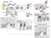
Here is a diagram that shows the basic points, with the seperate reg and rec. It has the TCI in a box, it has the later combo reg/rec in a box.
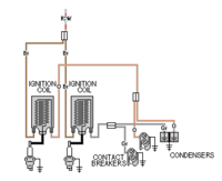
Start by looking at the charging system. On the points, hooking the stator to the rectifier is pretty straightforward. The three white wires to the three white wires. Red to battery. The Black to ground.
The brushes hook up just as easy. The green wire to the regulator, black wire to ground.
The brown wire on the reg hooks to power after the main switch. Once you get these all wired up. Hooking the ignition is easy too. Run w ire from the battery to a 20 amp fuse, from the fuse to the main switch. From the main switch power goes out on the brown wire. Hook all you fuses to this brown wire. Each fuse runs a seperate circuit. use a ten amp fuse and run a wire to a kill switch, from the kill switch to the ignition. On points , the coil. On a TCI the coil and the TCI box.
Once you get the ignition wired it should start. Use the kick start till you get the e-start wired.
Once you get it running check the charging system for proper function.
Once you get it to run and charge you can hook another fuse to the brown wire and run power to the lights. I would use an on/off switch , from the on/off switch to the dimmer switch and the tail light. From the dimmer to the headlight.
Make sure you have good grounds on the lights.
You can add brake light switches easy too. A fuse, or hook to your lighting fuse. Run power to the switches. From the switches to the brake light.
Once you get that far adding any other lighting you want is just as easy. Add a fuse, run some wire, switches, good grounds.
One thing yoiu might want is to have the horn. Run it the same way, power to a fuse, to the horn then to a button, from the button to ground.
This should get you started. Just remember that the word circuit comes from the same root word as circle. Power has to travel in a circle. Starts at the battery, goes out to a control, to a load, from the load back to the battery.
Leo
 

Attachments

  • 314w9s3.jpg
    314w9s3.jpg
    135.4 KB · Views: 208
I think Leo's above summation should be a sticky in and of itself. Like a "read this first" kind of thing. Short enough that there's no reason a person can't take the time to read it.
 
alright so Im stumped. Wiring my bobber ('75, Pamco, stock reg/rect). Starts and runs fine. But when it sits over night with the ignition switch off, the battery dies. Unplug either the battery and it will not lose power. Im using a diagram very similar to this

simplifiedWiring_fuseblock.jpg


Except I dont have headlight and tail light wired in yet. And I am using this ignition switch. With battery connected to the left terminal and Pamco connected to the right terminal.

large_341_341_emgo-universal-ignition-switch-3-position-4.jpg


The regulator and rectifier do not need to be disconnected by the ignition switch right? (they dont draw power when the bike is off, correct?) What is drawing power when the switch is off? The only thing I can think of is the switch is hooked up wrong. But this is (how I believe) the directions said to wire it.
 
Oh, and I dont have that kill switch in there. I should be able to just to the key to off to kill the bike, correct? That cant be the problem, can it?
 
That Diagram is for a PMA. If your using the stock reg and rec then you are not using a PMA.
Yes when the bike is off no power should flow back through the rec. A shorted diode can leak power though. Hook the battery up and unplug the rec. If the battery holds charge you found the problem.
You can replace the stock rec several ways. Spend a lot of money and get a Combo reg/rec, Get two bridge rectifiers from Radio Shack or get a three phase bridge rectifier off Ebay for like $5.
Leo
 
Wow, this sight is fantastic. It took me about 5 minutes to find the answer to my wiring question. These colored diagrams walked me right thru it. I'm restoring a 1982 heritage special. Alot of wires and parts were disconnected when I got the bike. Thanks so much for posting these diagrams. Sure did help me.:bike:

Posted via Mobile
 
I use 14 gauge from battery to main fuse, then to the main switch, on to the fuse block. From the fuse block I use 16 ga for the higher draw circuits. As in headlight, ignition, turn signals, horn. I use 18 ga for the lighter draw circuits, brake, tail lights, instrument lights.
I use 14 ga for most grounding.
If you run LED lights then the wire can be even smaller.
The only place that gets heavy wire is the battery cables if you use the e-start. Here going a bit bigger than the stock 8 ga cables I like a 4 ga cable. I run one from a starter mount bolt straight to the battery ground. This gives a cleaner ground path for the starter. One cable has fewer connections than from the starter to engine, through the mounts to frame, frame to cable to battery. Helps the starter work better.
You can find a chart that lists the current a given wire can carry. I thought I had one somewhere but can't find it.
Using too heavy a wire can be too stiff and won't flex under vibration. This leads to broken wires.
Cheap wire has less and thicker strands than more expensive wire. Some battery cables have like 20 strands of wire for a 6 ga cable, Some of the expensive cable have like 1600 strands of wire in the cable. The more strands in a wire is more flexible it is. So buying a better wire will save problems down the road.
Leo
 
Back
Top