some wiring diagrams

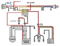
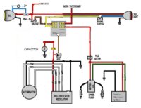
- you can remove the safety relay ... cap the yellow wire from the alternator and wire the solenoid directly from the starter button...the safety relay cuts power to the solenoid once the alternator is spinning fast enough to produce enough current

This interests me for my '83. It would be convenient to bypass all this extra stuff but not get into a total simplified rewire now.
I capped the yellow wire from the alt and my charging issue disappeared, though the headlamp and guage lights aren't lighting. Seems the starter lockout relay diode (part #4 H 7 01 omron 2761D9) went south on me. At least that's what I think it is.

Any help appreciated.
Rick
 
So I had some problems when I went to wire Mikes mini speedo and tach on the bike. During the process, I accidentally let wires cross and it blew several of the fuses. After replacing the fuses, now the electric starter and the kick start will not work. Since I am no expert at all when it comes to the electrical, I am at a loss of where to start. Could anybody help me with that?
 
Hello all

Just wondering if someone can take a look at my proposed wiring diagram and let me know if it looks like it will all work?

I took bits and pieces from two different diagrams and mashed them to basically add an inline fuse holder and rerouted the reg/rec fuse. :D

Also, I am assuming that I will be able to use this setup with a battery replacing the capacitor with no issues, correct? :shrug:

Thanks in advance
 

Attachments

  • mywiring.JPG
    mywiring.JPG
    88.4 KB · Views: 1,743
- i dont much see the point of running the capacitor off a key...not a battery
- and id be tempted to connect the capacitor straight off the rec-reg, both somewhere with airflow
 
- i dont much see the point of running the capacitor off a key...not a battery
- and id be tempted to connect the capacitor straight off the rec-reg, both somewhere with airflow

umm...yeah I see what you mean :doh:

How about this setup? :shrug:
 

Attachments

  • mywiring.JPG
    mywiring.JPG
    83.7 KB · Views: 1,277
Hey guys! Final got to wiring! Few Q's. ..... in post 6 on the stock alt, ignition, starter. What is the pick up coil? I have a black orange and grey in a black box on top of the alt / stator is that where the pick up coil is run to? Also on my cdi there is a white wire with black does that get capped? Thanks in advance......

Posted via Mobile
 
xs650_electrical_3.gif


- pickup coil is the little box on the alternator

- TCI
2-16-4053.jpg


- the wire that gets capped is the yellow from the alternator that went to the safety relay
 
OK I was guessing that was the pick up. So how do I wire the the black, orange, and grey to the black/white, red/ white, and green/ white? And does the 7th wire on the ignition unit get omited or where does it go? Its white with a black line in it.

Posted via Mobile
 
- B-W, W-R, W-G all go to the pickup
- B goes to earth
- O and R-W go to the coil
- the second B-W went to the sidestand switch-this can be cut

- pay to look at a wiring diagram to find which W-B is cut...the 7 wire TCI is from an SJ-SK
 
I understand the about diagrrm but my pick up coil has all solid colors on it and they are black orange and grey. Which colors goes to the b/w,r/w,g/w. Does the black go to b/w, grey to green/ white, and orange to r/w? The bike is an 83 heritage special.

Posted via Mobile
 
- im not 100 percent certain but i think that when you look into the plug end that comes from the pickup the coding should be

w-g I _ I w-r​
b-w​
 
I have know idea what that means!? Damn I though this was going to be simple! hahaha anyways I am still confused as ever. I will have to look at it again when I get home. I wish I knew where them 3 damn wires went! On the older models are the pick up coild red/white green/white and black/white? If so that would be simple.
 
- im not 100 percent certain but i think that when you look into the plug end that comes from the pickup the coding should be

w-g I _ I w-r​
b-w​

- your pickup should have a 3 point plug on the end of the cables coming from it... I_I ...when you look into it so the contacts make a U the colour coding coming from the TCI should enter the plug so the white-red is on the rhs
 
. Hope that's right! Gonna try it tomorrow. Don't want to put bad info up.

Posted via Mobile
 
Last edited:
So I'm gonna hook it up like posted above unless there is any objections?!? Hope I don't burn anything up!

Posted via Mobile
 
still on the same diagram as above. I wired it this way and i am now popping 20a fuse. i rode it for about a week with no problems. Come home from rockerbox and it keeps popping. Everything is solderd and the joints are double heat shrunk. only passed thru metal once and it is heat shrunk and has a grommet in the hole. I dont have a relay between the starter. could that be it? or a bad R/R? I thought it was the key switch but a new one only worked for a few seconds. Now as soon as you turn on the key it pops. Please advise.......Thanks!
 
Does anyone know why I'm pulling 25 to 29 amps thru the main power wire? It wired like above.

Posted via Mobile
 
for the condenser, does it matter which coil lead goes to which condenser lead? wanna make sure if it's important or not before i go to tearing and cutting wires....
 
Back
Top