some wiring diagrams

hi Travis, thanks for the response and taking the time to check it out. Much appreciated.
On mine, that wire is actually mostly white - almost just like a candy cane.

ok so I just realized. I've got it wired wrong. I didn't even realize those "red" wires had a white stripe on them.
So, I've got this thing wired very, very wrong right now.
Crap too, because I spent a lot of time creating a nice "T" into the brown wire for the "W/R" which I confused with "R/W".
:doh:
Anyway, VERY happy I asked...and thanks again for pointing this out to me.
 
Yeah I should have mentioned something about not confusing the R/W wire with the W/R wire. That's what was kind of throwing me off for a bit too. I'm glad you got it figured out!
 
I "colorized" that diagram I was talking about in the previous post and moved a couple items so that as a whole it all made more sense to me, as someone with practically no wiring experience.

If admins need to, for whatever reason, please delete it.
(i'm almost certain I didn't change anything except color and position of battery and coil.
(the reason being to kind of show those items "where" they are, on the bike)

full
 
I have an 83 heritage specail and I'm going to try to wire it up by myself. I'm absolutely horrible with wiring but I'm gonna give it a go anyway. I'm only running a headlight/taillight and the bike will be kick only. I'm going to try to wire up the lights, ignition,and brake switches on my workbench using my battery just to make sure everything is working properly. Once everything is ok and working I'll hook everything up on the bike. I have several questions before I get started.

1. From what I'm reading I think I'm going to use 14 gauge wire. Is this heavy enough?

2. My taillight and headlight are swap meet buys and I want to make sure they work before I wire them up. Can I test them by putting the positive wire on the positive terminal on my battery? If that's not a good idea how can I test them?

3. My headlight has one white wire coming out of it so I assume the headlight ground itself. right?

4. I have a lowbrow ignition switch and I'd like to know to wire it up correctly. There are three screws on the back of the switch. They are labeled B, IG, L. How should I wire this since I'm only using a kick start?


This is the diagram I think I'm going to use.
Thanks in advance guys, I appreciate the help.

650wiringchoppervh0.jpg
 
2. My taillight and headlight are swap meet buys and I want to make sure they work before I wire them up. Can I test them by putting the positive wire on the positive terminal on my battery? If that's not a good idea how can I test them?

I'm like the idiot on this thread so you may not want to pay attention to me, but as far as testing the tail light - I did it that way. Just make sure it (Tail light) is grounded, and that the battery is grounded.
 
Hello, forum. I'm brand new here and so far this site looks great! I just picked up my first Yamaha. 1975 xs650 and it runs great. It's got the banshee conversion done to it by the previous owner, but I got no lights. I ws getting ready to start tracing wires when I noticed that the capacitor looks like it broke loose from the bottom. I know these store energy, will it zap me if I touch it? Is it only connected from one end? On the broken end, there looks to be some kind of soldered nipple that looks to head to ground. capacitors.jpg I tried to attach a picture of what I think I need. ANY help is well recieved. Thanks!
 
Newb alert. Not afraid of wiring, but it has been awhile.

Batteryless, no turns, kickstart only, Banshee swap, with Pamco ignition.

Is this 100% correct?

I found a similar one in the alternator tech page AFTER I altered this one. Do I need to add anything? Can I delete anything? I am thinking of rebuilding the whole harness, but first it will be just cut and discard. :D

Would the key be necessary at this juncture or could I just delete it and run the red and brown together?

And to turn off the bike, just flip the kill switch? Or should I leave the key for extra security?

Thanks in advance for your input!

206377_1764695315319_1177209439_31644911_1144640_n.jpg
 
In that diagram it has the stock regulator, rectifier and alternator.
The stock reg, rec and alternator are a feild excited alternator. This means it needs a battery to power the rotor thru the brushes, this makes the rotor a magnet so as it spins inside the satator it excites the stator into making electricity.
If you want to run without a battery you need to convert to a PMA, permanent magnet alternator.
This type of alternator does not use a battery and the brushes to make the rotor a magnet. The rotor has permanent magnets built into it.
So as it spins it excites the stator into making electricity. No battery needed, You do need a battery or a capacitor to help the regulator to put out a stable voltage.
Check out Punkskalar's PMA conversion thread. At the top of the page click TECH, scoll down to Electrical. #3 thread listed is the one to read. How to PMA swap or Banshee Swap.
 
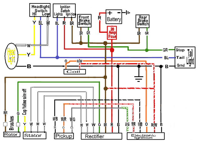
hi folks, I have yet another question about the red/white wire that comes off the stock ignition box, using that 2nd diagram in this thread, in a colorized version I showed above (and have attached below).
That red/white wire has to make a "T". One branch goes to the coil and one attaches to the brown wire.

The thing that is confusing me: doesn't the fact that that wire goes to coil from IG. box mean that the coil gets some kind of "info" from the ignition? That has to do with timing? So if it is attached to that brown wire TOO (as in the diagram), isn't the coil getting constant power then, with key on, just by virtue of the red/white wire being T'ed into the brown wire prior to being attached to coil?

Could in theory with this diagram, the red/white wire, the brown wire and the coil wire (not the orange one, the one that attaches to red/white) just all 3 be twisted together?

I'm not understanding what the brown wire does for the red/white wire and coil. If it is simply powering the coil, then why go to the ignition at all?
Again, my thought is the ignition is powering on and off with the timing, so the coil knows when to fire. But how can it do that, if it is tied directly into that brown wire as the diagram shows?

Or maybe I'm misunderstanding, and all the brow wire is doing is supplying power to coil and to Ignition box? If that's the case, couldn't I run a shorter wire to the coil, if all it needs is power from the brown wire?
Like, INSTEAD of the coil getting power via this circuitous route, down to ignition box and then back up to coil under gas tank.... couldn't I just provide a "T" off the brown wire, closer to the key switch?

I understand the brown wire pretty well in some ways (thanks to the efforts of several of you) but I'm just not sure about the red/white wire on IG and the brown wire. Is brown wire just "feeding" Ignition box power? or is red/white wire also providing electrical "info" to coil, re: timing?

sorry to be so dumb, but I really have pondered this a lot today.
It seems so simple, and yet....
:banghead:
:confused:

Making an intelligent connection between red/white wire on IG, brown wire, and wire to coil (as in this diagram) is baffling me. Could those 3 wires just be twisted together? or must they be "t'ed" in some certain order?

ps: I'm not going to just twist them together, but I just want to know if , in essence, that is what is being accomplished by wiring as in the diagram.

thx!
 

Attachments

  • wiring color annotated.jpg
    wiring color annotated.jpg
    95.8 KB · Views: 597
Em, the connections can be anywhere as long as they're there. A schematic is drawn in the way that makes it easiest to understand, hence the right angles and stuff. The actual physical connections can be anyplace. For example the coil and the tci wires could both just go to the battery - electrically it would be the same. There's no "order" the wires have to go in. There is an order to drawing schematics, to make them easiest to follow.

The other question, the "info" from the tci, the tci takes the orange wire briefly to ground and and then back up when it's time to fire the cylinder. The other side is always +12. The resistance of the coil is what makes that possible; couldn't happen with just a short piece of wire. Not for very long, that is.
 
Em, battery power flows to the main switch. It then flows out on the brown wire. This brown wire feeds power to the coil on the red/white wire. The red/white wire also sends power to the TCI box. The TCI box uses this power to run the electronics inside the box.
The pickups on the stator sends signals to the TCI box that tell the TCI box the engine position and rpms.
The transistor in the TCI box does what the points do. As it turns on/off is the same as the points closing and opening.
Power flows to the coil on the red/white wire. From the coil to the TCI box on the orange wire. Inside the box the orange hooks to one leg of the transister. The transister is turned on and letting the power go to ground. This creates a large magnetic feild in the coil.
When the TCI box gets the signal from the pick up telling the box that the engine is at 15 degrees before TDC the box turns the transister off. This stops the flow of power, collapsing the feild in the coil, this generates the high volt in the secondary of the coil and this high voltage makes the spark plugs spark.
The pickup has two coils inside one unit. As the engine is running the TCI box measures the time between the signals from the two coils. It uses this time difference to calculate engine rpms.
When the rpms reach 3200 rpms the TCI box advances the timing. The same as the mechanical advancer for the points.
Hope this helps.
Leo
 
XSLeo thanks, and just so you know, I read and re-read your other thread about what happens when the key is turned. It's hard for me to wrap my head around it. But please know that your efforts are much appreciated.
:)
 
need some help. i did one of the simplified diagrams off of this thread and for some reason i only get spark when i turn the keyed ignition from off to accessory and then when i turn the key to start i have no spark when the engine cranks it is only one spark and thats it it does the one spark also when i turn the key from access to off i have no clue what is going on i have checked the wires and everything seems to be fine can someone please help me out
 
Back
Top