Sparking with Lucille - the PAMCO installation!

MaxPete

Lucille, Betty, Demi, Gretel & Big Sue money pits.
Top Contributor
XS650.com Supporter
Messages
10,080
Reaction score
35,153
Points
813
Location
near Harrow, ON, Canada
CHAPTER 1 - The PAMCO System & the Coil Mounting Plate
As part of my on-going program to resurrect my red 1976 Standard (aka Lucille), I had bought a PAMCO ignition system complete with the electronic spark advance module known as an E-Advancer. I bought the kit from XS650 Direct which is the Canadian affiliate of MikesXS.
They offer several different PAMCO kits and the one I bought is part number 14-0910 which includes an electronics module (the blue box in the photo below) that replaces the mechanical spark advance system on pre-1980 XS650s. For 1980 and later bikes, a different kit is required - although those bikes actually came with a factory electronic ignition system called a TCI - so I don't completely understand why you'd want to buy a PAMCO to replace the factory ignition system since it also includes an electronic advance system and is reported to be maintenance free and highly reliable.

Here is a photo of the 14-0910 kit from the XS650 Direct website.
PAMCO+E-Advancer_Kit - 14-0910.jpg

The kit includes all of the actual ignition system components - BUT - there are some additional wiring and hardware items that you will need to supply, including:
  • two male bullet connectors to connect the sensor module to the red-white ignition system wires on the bike (there is a double-female plug located under the fuel tank to which you will connect the system and the main coil power wire WITH A FUSE);
  • two female spade connectors to connect the little blue E-Advancer box outputs to the new dual-output coil;
  • a modern blade-style automotive fuse holder and a 7.5 amp fuse which protects the delicate PAMCO system in case the coil fails (otherwise, a current surge could reportedly cook the unit);
  • a small metal plate and two 24mm long stand-offs on which to mount the coil under the fuel tank;
  • two 45mm long M6x1 SHCS and two 15mm long M6x1 SHCS to secure the coil to the mounting plate and the plate to the bike (BTW - a SHCS is a socket head cap screw or an "Allen" bolt);
  • some zip-ties to lash the wiring down so that it doesn't get tangled up with anything.
COIL MOUNTING PLATE
The new ignition coil is fastened under the fuel tank using the original mounting pad for the left hand OEM coil. The exact dimensions of the plate are really up to you but as many other forum members have done, I used a piece of 1 inch wide x 1/4" thick aluminium with a drilled and tapped a pattern of holes to receive M6 SHCS so that I could use the same metric tools as fit the rest of the bike. It is very important that the coil be mounted securely. It is fairly heavy and puts out around 50,000 volts - so you do not want it flopping around bashing through the underside of your 40+ year old fuel tank.

Here is a photo of my el-cheapo shop drawing of the plate.

Coil_Mounting_Plate - dwg.JPG


Sorry this drawing is rotated - but I think you get the idea. The only "critical" dimensions are the spacing of the "outer" holes at 102mm - to match the mounting pads on the coil and the spacing of the "inner" hole pattern at 54mm to match the mounting holes on the bike's coil mounting pads. The relationship between these two hole patterns is not critical and it will work if you do it as shown in the drawing.

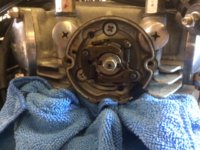
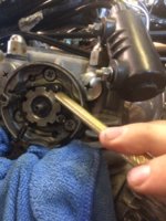
Here are photos of the plate - ignore the extra holes - I was experimenting with several inner hole patterns to move the assembly around under the tank. Also below are photos of the coil in place - from the LH side and from the RH side of the bike. The stand-offs shown in the photos are two pieces of 10mm dia. steel tubing each of which is 24mm long.
Coil_Mount-photo.JPG

Coil-LH-side.JPG

Coil-RHside.JPG

In the next chapter - I will describe the installation of the mechanical components of the PAMCO ignition system.

Cheers,

Pete
 
Last edited:
CHAPTER 2 - Installing the PAMCO Components
Installing the PAMCO mechanical components is not difficult, but there are a couple of tips I will show you and also - there is one somewhat challenging task which I will also describe. Basically, you will remove all of the mechanical components of the stock XS650 ignition system from the camshaft portion of the engine.

The OEM Kettering ignition breaker points are mounted on the LH end of the cam and the mechanical advancer unit with its fly-weights and springs is mounted on the RH end. A long steel rod runs through the middle of the camshaft. It is supported by three internal bronze bushings inside the camshaft. The rod connects the mechanical advancer unit on the RH end of the camshaft to the points actuator cam on the LH end. That rod rotates as the engine speeds up (and the fly-weights move outwards) and that rotation causes the points actuator cam to rotate - which changes the timing of the engine. It all works great - if everything is adjusted properly, the springs are not too weak or too strong and there is no corrosion anywhere....

In the PAMCO E-Advancer system - only that internal rod remains to connect the LH sensor rotor to the camshaft. The stock mechanical advancer unit on the RH end of the camshaft is removed and replaced with a simple rotor that just spins with the camshaft and essentially doesn't do anything else except hold the sensor rotor on the LH side of the assembly.

Just to prepare you: the major challenges I experienced all involved the three tiny steel pins which stick out of the camshaft in a radial direction. One of these pins is on the LH end of the camshaft and two of them are on the RH end.

Keep track of them - these little buggers are small, yet vital - and they're easy to lose because at least two of them are only loosely retained in their bores and can simply fall out (don't ask me how I know this).

Here is a photo of the two RH advancer side pins - we will be discussing the lower (and longer one) more - later.
Advancer_Side_Locating_Pins.JPG

In any event, that is why I am so grateful that I bought a couple of extra pins (shown in the photo below). They're cheap - and so when you're ordering your PAMCO kit - do yourself a favour and buy 2-3 of these GD frickin' pins.
Ignition_Locating_Pins - 14-0653.JPG


NOTE: no matter how much you want to - DO NOT remove the spark plugs from the engine at any time during the installation of the PAMCO system. There is simply too great a chance of something going down that spark plug hole - with tragic results.

Anyhow, here are the steps to install the mechanical components of the PAMCO system:

1) Remove the two chrome camshaft end-covers and the alternator cover (you DO have the correct JIS screwdrivers - don't you??? ;));
On the LH end of the cam, you will find the points plate and its rotor cam. I suggest that you rotate the crankshaft to orient the slot in the points actuator cam is oriented upward - as it is shown in the photo below (which has been lifted from the web). The key thing is to have it oriented between say...10:00 and 2:00 o'clock so that the damned pin doesn't fall out and get lost (like mine did).
XS650_Points-in-place.jpg

To orient the points actuator cam slot - simply use a 17mm wrench to gently turn the crankshaft (using the big nut inside the alternator cover) clockwise - until the slot in the points cam rotor is oriented UPwards as described above.

2) Mark the position of the breaker points mounting plate relative to the cam housing - juuuust in case you have to re-install it somewhere - like beside the road, at night, in the rain. To do this, I simply put a little dab of office "white-out" correction fluid across the joint between the points plate and the fixed cam housing - and then made a scriber scratch in the white-out (see the photo). That would provide a timing setting close enough to get me home if something bad happened.
Points_Index-Mark.JPG


3) Remove the hex nut that secures the points rotor cam to the end of the camshaft - and DO NOT allow the tiny pin that is invisible - but is located inside the rotor - to drop out. It is extremely difficult to locate one of those pins if you drop it - believe me. Then just slide the cam off the end of the camshaft and set it aside;

4) Remove the points plate as a unit (i.e. do not separate the two sets of points) and disconnect the points electrical connection and clean the pocket in which the points plate had been located using parts cleaner and a little brush (now would also be a good time to check the camshaft oil seal);

5) Install the PAMCO sensor plate where the points plate had been located - and rotate it to a position in the middle of the adjustment range. Now tighten ONLY the upper PAMCO plate securing screw. You will be moving that plate a bit when you do the final timing adjustment and you don't want to be wrestling with two screws.
As noted, you will be using a timing light later to dial it in exactly, but the engine should start-up OK at this timing position.
PAMCO_Sensor_Installed.JPG

NOTE: I was surprised that my PAMCO sensor plate looked different from those in the instruction photos - but apparently, they are from an earlier version or one that does't use the E-Advancer unit - so no worries.

6) Now install the larger diameter and thinner PAMCO rotor as shown in the instructions - making sure that you capture the tiny locating pin in the assembly, slip on the washer and nut and tighten it all up. I couldn't find a torque specification - but good & snug will do it. These parts are small, and not heavily loaded - so don't go all Neanderthal on them.
PAMC_Sensor_Rotor.JPG


OK - so I just got the dreaded 10,000 max. number of characters warning - so I have clipped the rest of Chapter 2 - and put it into a separate post below.

Pete
 

Attachments

  • XS650_Mech_Advancer.JPG
    XS650_Mech_Advancer.JPG
    140.1 KB · Views: 523
  • Mech_Advancer_Removal.JPG
    Mech_Advancer_Removal.JPG
    61.5 KB · Views: 534
Last edited:
HOLD ON GUYS - I'm not done with Chapter 2 yet!! I got the dreaded 10,000 maximum number of characters warning.

As for the comments:
  • Johnny - the pin did NOT go down the hole. I lost some photos and had to lift that one from the web. I never removed my plugs during this entire job. :geek:
  • I think that was a different coil - this one has fairly beefy terminals I'd say but yes, I will be securing those terminals for sure. WER & Gary - I certainly believe in a pound of prevention before a ton of cure! ;)
  • the barn thing was NOT fun I can assure you Dude. :(
Meanwhile, back at the ranch....

CHAPTER 2 - continued....
7) Now go around to the RH side of the bike where the mechanical advancer is mounted on the end of the camshaft. You will be removing nearly all of that gubbins and carefully saving it - juuuussttt in case.
View attachment 104765
To remove the mechanical advancer unit - start by removing the the nut in the centre of the photo and slide the double-slotted rotor off the end of the camshaft. Then you will need to GENTLY remove the advancer springs from their perches - those things are precious so go easy on them. Don't loose the tiny little spring clips that secure the weights and the 3 or 4 thin Belleville (spring) washers that live under the advancer weights - those are also hard to find and necessary in case you ever have to reinstall the mechanism.

Now stop, have a cool one and go on to Step 8.

NOTE
: I packed a dampened blue shop rag below the mechanical advancer to catch any tiny little bits that might drop out during the job - and I suggest you do the same. Also - I repeat - do NOT remove the spark plugs. If one of those tiny hardened pins drops down the hole - you will have to remove the cylinder head to retrieve it - or risk fatal engine damage when you start the bike.

8) At this point, you should see a big nut with notches around the outer diameter. This nut holds the remaining part of the advancer on - and so you need to remove the nut. There is almost certainly a special Yamaha tool for this purpose - but nobody I know has one - so you can just use a punch (brass would be best because it is softer than the steel nut).

To remove the nut - seat the end of the punch into a convenient slot - and make certain that the punch is touching ONLY the nut itself and not any part of the advancer mechanism plate.

Yes, I realise that in the photo below, I am about to knock on of the advancer weight pivot pins off - but I couldn't hold the camera and the punch in a more realistic orientation.


Now just give the end of the punch a couple of firm taps with a hammer and the nut should loosen off and then it will be easy to remove it the rest of the way by hand.
View attachment 104766
NOTE: The plate that is secured by the slotted nut will still be firmly seated on the cylinder head. Just give it a little squirt of WD40 or something, wait a few minutes and then GENTLY pry it off with a thin slot screwdriver. I was worried that mine was seized in place - but it came off with just a little persuasion.

9) At this point - you are looking at the end of the camshaft with its two tiny little locating pins sticking out.
View attachment 104759
NOTE: there should be two pins and they are NOT lined up. Stare at the photo till you see that. Now look at the PAMCO advancer side rotor (the smaller diameter but longer of the two PAMCO rotors) - and observe that it also has two spots for those pins - which are also not lined up.

The problem is that the longer pin on the outer diameter of the camshaft is TOO DAMNED LONG to fit the mating slot in the PAMCO rotor.

On my bike, the points side locating pin literally fell out and got lost (thank God for the spare pins that I bought with my PAMCO kit) and the shorter pin on the advancer side was very easy to remove with pliers - but the longer pin (the one that is "sometimes" too long - and is pointed straight down at 6:00 o'clock in the photo above) - was stuck firmly in place.....which brings us to...Step 10.

10) The PAMCO instructions suggest that because the longer pin is "sometimes" too long, you may need to "file it" to a shorter length. Well, I don't know what sort of file one might use in there, but I found that the only thing that I could fit into the location of the end of the pin and that would reduce the length of that pin was a grinding wheel on my Dremel MotoTool. For that reason, I kept the blue rag in place to catch any grinding debris.

The job only took a few minutes - but it was not fun because there is an important and delicate 41 year old camshaft oil seal right behind where I was grinding - and the thing is - I had a second spare pin that I could easily have used - had I been able to remove the one that was stuck into in the GD%##@$ camshaft.

The best solution would be if PAMCO simply made the danged slot in the rotor the correct size to fit that long pin.

Anyhow - once you've gotten the pin shortened, or if you're lucky, replaced it with the correct length shorter pin, you simply slip the PAMCO advance side rotor on and secure it with the nut - but be certain that it is seated all the way on and that BOTH locating pins are captured within the assembly.

That's it folks - you're done the mechanical part of installing the PAMCO with E-Advancer!

In Chapter 3 - we'll dig into the wiring!

Cheers,

Pete
 
Last edited:
Hi all: thanks for the great suggestions and for the kind words.

It finally stopped raining and so I just took Lucille out for a little toot - and all I can say is....wow. She starts instantly, revs willingly and runs great on the road. I putt-putted around the neighbourhood a bit to ensure that nothing bad was going to happen and then I went out onto the nearby freeway and got her spooled-up to...well, pretty darned fast and she runs better than ever..

Anyhow, I am tired and my knee is sore, so I'm going to hit to hay and tackle Chapter 3 tomorrow.

Cheers,

Pete
 
Here is a link to a thread complaining about the terminals falling off Mikes aftermarket TCI dual out put coil. .......He calls this a "High output replacement coil",
Part
17-6803.........This is not the one Pete is using...............

Has any one had problems, or have proof this Altermate High output Coil has the same problem..
Part
17-6903
Nope just piling on.......... i knew one of those coils wuz crap.
 
Hey hey!!!

Guess who just woke up after a long winters nap....and a bout of leaky float bowls. I’d post a video but I can’t remember how!

What I can say is that she starts and runs fantastically well, and my first ride was a delight!

Looks like I’ve got myself a ball game.

Pete
 
Way to go Pete! Great news!
Upload the video and publish it to YouTube then copy and paste the link in a post here.
 
Back
Top