Sprocket Gearing

79josh81

XS650 Addict
Messages
427
Reaction score
419
Points
63
Location
Kiel, Wisconsin
Ok, so I’m working out the details on some sprocket gearing to potentially run a jackshaft with a wide tire build. On my current bike, I have a 17 tooth front sprocket and a 31 tooth rear overdrive sprocket. The gearing ratio of that combination is 1.82.

I would like the bike I’m building to have around the same gear ratio but I’ll be using a Harley style wheel on the rear with a Harley 46 tooth rear sprocket. In order to get around the same gear ratio, according to the numbers, the front sprocket would have to be a 24 tooth sprocket which would give me a gear ratio of 1.91.

My question is, if I run a chain from the 17 tooth front sprocket to a 17 tooth sprocket on the jackshaft, and then run a 24 tooth sprocket on the jackshaft going to the 46 tooth rear tire sprocket, will that give me a gear ratio of 1.91 to the rear tire? It sounds right in my head but I’m not an engineer so I don’t know if I’m missing something here. Here’s a “not to scale” pic to make it easier to understand.

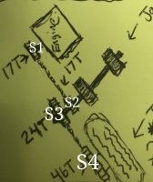
B3DACAC6-EA05-4462-A9B7-AAEF5EC8D16C.jpeg
 
Use the tooth counts of your sprockets S1, S2, S3, S4.
SprocketRatios.jpg

Then, the ratio you're looking for is:

(S2 * S4) / (S1 * S3)

In your particular case,
With S1=17, S2=17, S3=24, S4=43
(17 * 46) / (17 * 24) = 1.917

Or, the alternate:

(S2 / S1) * (S4 / S3)

(17 / 17) * (46 / 24) = 1.917
 
Use the tooth counts of your sprockets S1, S2, S3, S4.
View attachment 133941

Then, the ratio you're looking for is:

(S2 * S4) / (S1 * S3)

In your particular case,
With S1=17, S2=17, S3=24, S4=43
(17 * 46) / (17 * 24) = 1.917

Or, the alternate:

(S2 / S1) * (S4 / S3)

(17 / 17) * (46 / 24) = 1.917

I just did the math by keeping the front sprocket size the same as the inner jackshaft sprocket size (17 tooth) and then just played around with other sprocket combinations until I found the right ratio. I actually was able to find a 25 tooth sprocket instead of the 24 which brings the ratio about as close as I can get it to 1.82 to 1.84. Your above equation though is what I assume is the correct engineering equation to gear that set up huh?
 
Would it be better to flip the rear wheel so it's sprockets are on the left side? That way you would have a sprocket on both ends of the jack shaft. I think this would better distribute the load to both jack shaft bearings.
Also you might not have room enough to get both sprockets on the same side of the jack shaft.
Leo
I’ve thought about that a lot also. I feel like if I flip the tire around though, that spreading the two jackshaft sprockets that far apart might create a larger twisting force on the jackshaft’s shaft maybe? I don’t know. What do you guys think? I guess it would all depend on how much room I have on that side like you said and how far apart the sprockets end up with the offset if they’re on the same side.
 
Last edited:
Would it be better to flip the rear wheel so it's sprockets are on the left side? That way you would have a sprocket on both ends of the jack shaft. I think this would better distribute the load to both jack shaft bearings.
Also you might not have room enough to get both sprockets on the same side of the jack shaft.
Leo
That will not be the case. The chain from the 17 tooth countershaft sprocket is pulling the shaft forward, while the chain to the rear wheel tries to pull the shaft the other direction. So the forces from the chains are pretty much cancelling each other out for the suggested 17/17/24/47 tooth setup.The actual bearing loads on a jackshaft will result from the different sprocket sizes, and from the spacing between the sprockets. Your suggestion would increase the bearing loads, basically subjecting the LH end of the jackshaft to the same load as the countershaft, and the RH end to around 71 percent of that. Just make a sketch, using force vectors at the suggested sprocket locations, and it should become pretty obvious. With 40 mm offset between sprockets, the resulting bearing load on the LH end may be around 40 percent of the countershaft bearing load, and very low at the other end. If the OP wants any calculations or bearing size recommendations, I can take a closer look at this some later day this week,
 
Last edited:
That will not be the case. The chain from the 17 tooth countershaft sprocket is pulling the shaft forward, while the chain to the rear wheel tries to pull the shaft the other direction. So the forces from the chains are pretty much cancelling each other out for the suggested 17/17/24/47 tooth setup.The actual bearing loads on a jackshaft will result from the different sprocket sizes, and from the spacing between the sprockets. Your suggestion would increase the bearing loads, basically subjecting the LH end of the jackshaft to the same load as the countershaft, and the RH end to around 71 percent of that. Just make a sketch, using force vectors at the suggested sprocket locations, and it should become pretty obvious. With 40 mm offset between sprockets, the resulting bearing load on the LH end may be around 40 percent of the countershaft bearing load, and very low at the other end. If the OP wants any calculations or bearing size recommendations, I can take a closer look at this some later day this week,
So you’re saying it should be fine if both sprockets on the jackshaft are on the same side of the shaft? Keeping the sprockets closer together is best to minimize the twisting force of the front pulling forward and the rear pulling backwards? Honestly, “force vectors” are not something I’m familiar with. You sound like you know way more about this stuff than me that’s for sure. The most difficult thing I’m having trouble with is finding a pillow block with a bearing that’s rated for 7500 rpm’s or higher. I tried looking up a rating system or chart for pillow blocks but it seems to kind of be all over the place. I planned on using two finish bore sprockets, a keyway shaft, and two pillow block bearings to make the jackshaft.
 
You need bearings rated for the max load and rpm that they will see. I have the SKF bearing catalog available on board, and can have a look at the info there in a day or two. Note that SKF only do metric. Is your engine a stock 650, or is it hopped up?
 
You need bearings rated for the max load and rpm that they will see. I have the SKF bearing catalog available on board, and can have a look at the info there. Is your engine a stock 650, or is it hopped up?
Yeah it’s all stock. But I’m gearing the sprockets as you can see to keep the rpm’s down at highway speeds.
 
I see metric finish bore sprockets being hard to find too maybe? I just know I’ve spent hours trying to find what I thought would be some pretty basic parts.
 
Btw, your jackshaft won't be doing 7500 rpm. The primary drive ratio is 2.66, while 5th gear is near 1:1, dont have the exact numbers. In any case, 7500 rpm at the crankshaft then gives around 3000 rpm at your layshaft.
 
Btw, your jackshaft won't be doing 7500 rpm. The primary drive ratio is 2.66, while 5th gear is near 1:1, dont have the exact numbers. In any case, 7500 rpm at the crankshaft then gives around 3000 rpm at your layshaft.
I just literally thought of that and was going to say something. Lol So if I used a pillow block with a 3000 rpm rating or higher I should be good?

Any how here is a link to a pillow block I found that is rated at 7500 rpm (but the locking device on it is set screws which I’m not sure will work?)
https://www.mrosupply.com/bearings/mounted-bearings/pillow-blocks/131696_123806_dodge/

And here are the two sprockets I planned on using...
045C24CF-9E00-4B55-8CB0-58AEA7E36356.png
513077F3-D11F-4F67-BE3D-BB7B505F8E82.png
 
Thinking a bit more about a jackshaft setup. What if you skip the pillow block altogether, and go for a non-turning axle, then have the two sprockets joined together, with a suitable bearing setup? That way the axle and brackets will be a much cleaner/neater arrangement. A shaft and 2 of those pillow block bearings would look very industrial....
 
Last edited:
Thinking a bit more about a jackshaft setup. What if you skip the pillow block altogether, and go for a non-turning axle, then have the two sprockets joined together, with a suitable bearing setup? That way the axle and brackets will be a much cleaner/neater arrangement. A shaft and 2 of those pillow block bearings would look very industrial....
Yeah I thought about that. But then I have to figure out how to connect the two sprockets and the ones they sell that are connected to the same hub are expensive. I kind of wanted the “industrial” look too.
 
Those sprockets you are showing have only 1 keyway, while countershaft sprockets normally have 6 or more splines transmitting the torque from shaft to sprocket. I believe that a single key will shear in this location.
Yes, the crankshaft primary gear often has only one key, but a pretty big one. The engine torque is multiplied by the primary drive, and the first gear ratio, by a factor around 6 or 7, going by memory. So those industrial sprockets have no chance in your suggested setup. Maybe you can find a dual sprocket with the desired offset?

Well if that’s the case then that sucks because I already have those sprockets and a shaft to match because you’re the only person that’s said something like that after 4 weeks of discussing that set up on here and other places online. I'm not an engineer but wouldn't it take way more torque than an xs650 can put out to shear a 1/4" by 1/4" key in a 1" diameter shaft? See the example in this link: https://www.linearmotiontips.com/transmitting-torque-with-keyed-shafts/

I'm not going to act like I understand everything in these shear force equations on shaft keys, but the example they're using has a smaller diameter shaft and a smaller key size (which both reduce the maximum torque a key can take) than I'll be using and it says that it can take 674Nm of torque before it will shear. I'm using a 1" diamter shaft with a 1/4" x 1/4" x 1 1/2" long key. So shouldn't the 1/4" x 1/4" key be sufficient?
 
Yeah I thought about that. But then I have to figure out how to connect the two sprockets and the ones they sell that are connected to the same hub are expensive. I kind of wanted the “industrial” look too.

Hi josh,
arctic's right, the single key most likely won't cut it.
Try welding the sprockets together back to back and a big ol' Vee+fillet weld on the outboard end to join the sprocket pair to the shaft.
Sure you gotta renew the complete sprockets+shaft unit when the sprocket teeth wear out but that's 10,000 miles down the road, eh?
 
Back
Top