Started the Special ll refurb

flyerdon

XS650 Enthusiast
Messages
42
Reaction score
85
Points
18
Location
Gaylord, MI
DSC02934.JPG
DSC02973.JPG
DSC02972.JPG
For the past two days I've been labeling all the connectors and various electrical parts and identified where they are located/attached to the frame. Then I removed the entire electrical system. Next I removed the battery box, shocks, swingarm, and am now ready to remove the engine and the front end, hopefully to get the frame to the guy who will blast it for me. Luckily the swingarm must have been removed at some point in the past as it came out quite easily when I followed the directions on the forum. Grease was a sour brown substance but at least there was some there. In my case, the cross-over tube between mufflers was a challenge but I did get it off and one exhaust stud came out all the way instead of just the acorn nut but I'd rather have that problem than a broken off exhaust stud in the head.
 
Last edited:
…. aaah.. the memories..... I must have used a small case of zip lock bags... with hand drawn pictures..notes stuffed inside with the part... really saved me heart burn when it came time to put it all back together...
 
I decided to see what I could do with the rear wheel and fender. This poor bike spent a lot of time outside in the weeds from what I can see. There were small vines wrapped around the wheel spokes and up under the tank. I'm sure that wasn't from the guy I bought it from but probably the person he acquired the bike from because the PO had it titled in 2008 but he never got anywhere with doing much to it. Consequently the surface of almost everything is pretty oxidized or rusted. It had two flat tires so I doubt the guy I got it from ever rode it at all. Amazingly, the wheels are in good shape, some surface rust but inside it a lot better than I've see before with bikes that were as cruddy on the outside and although the carbs were in horrible shape, when I got them cleaned up and started the bike, it ran like a clock. Anyway, I put about 6 hours into the rear wheel/brake and fender and I not sure how much more time an effort I want to put into that, at least right now
 

Attachments

  • DSC02979.JPG
    DSC02979.JPG
    209.8 KB · Views: 179
  • DSC02980.JPG
    DSC02980.JPG
    185 KB · Views: 193
Hi Flyerdon, looks like good progress with the refurb and thank you for a very deja vu picture - interior of headlamp shell.

Takes me back to the time I had to rewire my 1970 Triumph TR6 650. The electrical system was bad, really bad. There was a horrible mixture of original 1970 wires with cracked insulation and black copper, plus a lot of makeshift wiring all done with white domestic wire, using domestic 'chocolate bar' connector blocks. The rectifier was the original, forty-odd years old - bent, rusty and corroded. The ammeter had been wired backwards so, when you started the bike, the drop as you depleted the battery looked like it was being charged. PO? A domestic electrician by trade . . .

Wasn't going to be easy - I had always avoided electrics on all bikes I had owned. Wiring diagrams filled me with trepidation. But no 2 ways about it, if it was ever going to be reliable, bike needed a complete rewire. So every wire was unhooked, numbered sticky tab attached, and detail of where it went written down on a very long list. As I removed wires, eventually many proved to be the other end of one already noted and the list could be reduced.

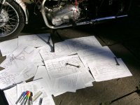
Then I started drawing wiring diagrams recording what I was pulling off the bike. These went through iterations as I realised many of the wires were redundant, for example where a faulty old wire had simply been duplicated with, you guessed, domestic white cable. Grew to enjoy using coloured pens to record the bike's nervous system - must have brought out the ten year-old in me - and by the end of the process felt I was beginning to understand it all. Picture I took back then shows a small selection of those diagrams and lists:


PICT1361.JPG
 
Just about everything is off the frame now except for the center stand, front forks and the motor, so I started to unbolt all the motor mount bolts and for the most part all was pretty easy except for the very front bolt holding the motor to the mount. The frame bolts weren't too bad but the one holding the motor to the mount was really stuck in there so I put plenty mouse milk on it and now it seems to be coming. I did notice while I had the left dover off that it appeared the little seal that the clutch pushrod goes through has been for who knows how long. On my particular bike the seal is yellow and I'm not sure if that's normal or someone put a seal in just because they had it on hand. Anyway, according to the diagram I am looking at from Babbitts, the seal is listed as Sd type 93102-08206-00. Does anyone know or can confirm that that number is correct for that particular seal? I want to replace it when I start putting things back together.
 
It would probable be a good idea to order a complete engine seal kit. Gasket set also. You will need them sooner or later.
 
That's the right seal part #. You may also need/want to replace the bushing behind it that the pushrod works through. I know Gary doesn't think the bushing needs replacing most of the time but on the couple I've done, they needed it. Here's a pic of the old one I replaced recently next to some new ones. You can easily see it's worn thin .....

ZfpKWJC.jpg


Also, the replacements we use are longer than the original so should give more support and last longer .....

st8JtC7.jpg


I went with a 12mm long one on this last job. 2M expressed some concerns about an oil feed hole inside the bushing bore and that a longer bushing may block it. I inspected the hole thoroughly and could see no oil hole. There's a step inside the bore to stop the bushing from being driven in too far .....

nSDp4tM.jpg


My best guess is that if there is an oil feed hole in there, it's in deeper, past the step, so a longer bushing blocking it is of no concern. The step is about 11mm into the hole. That means a 12mm bushing will protrude about a MM out of the shaft when seated to the step .....

2uTISgB.jpg


But that's OK, it won't contact the back of the seal because it has 4 little "feet" on it .....

iCH36co.jpg


I must say, I was quite pleased with my 12mm bushing, new seal, and N.O.S. long pushrod install. That pushrod was a perfect sliding/slip fit into the new bushing with absolutely no wiggle or side play.
 
OK, thanks for the info. That whole pushrod set-up seems over engineered to me. I really can't see the need for so many parts (two balls and rods) vs. just a longer rod. Maybe something inside the clutch mechanism itself requires this set-up but I haven't seen one quite like it before.
 
I finally managed to get the front engine mount bolt loose today after many applications of mouse milk then after it broke loose I still couldn't get it to come out. I drilled a hole through the engine case right where the bolt passed through on each side and applied mouse milk through those two holes directed to the bolt and after about six applications there it finally came out. Amazingly the bolt itself didn't look all that corroded but it was stuck like it was welded in there. After all engine mount bolts were out I was able to wiggle the engine out of the frame, very carefully. That's one hell of a heavy engine for it's size and I know I'll need help getting it back in. At 69, 150 lbs and 5'6", there's no way I could get that bugger back in. Here's a couple pictures of the frame as it sits now.
 

Attachments

  • DSC02988.JPG
    DSC02988.JPG
    211 KB · Views: 205
  • DSC02989.JPG
    DSC02989.JPG
    222.9 KB · Views: 173
Please excuse the :hijack: flyerdon.

... 2M expressed some concerns about an oil feed hole inside the bushing bore and that a longer bushing may block it. I inspected the hole thoroughly and could see no oil hole. There's a step inside the bore to stop the bushing from being driven in too far ...

My best guess is that if there is an oil feed hole in there, it's in deeper, past the step, so a longer bushing blocking it is of no concern. The step is about 11mm into the hole. That means a 12mm bushing will protrude about a MM out of the shaft when seated to the step ...

Great pic, 5twins! Looks like we can put this matter to bed. I'll update the pushrod bushing interchange thread on this issue.

http://www.xs650.com/threads/clutch-pushrod-bushing-interchange-thread.30549/
 
Last edited:
The tires and tubes are off the wheels and I've got the wheels pretty good. No bad pitting but there is a bit of light rust that is still visible if you're looking for it. Got the front end off and checked everything. The bearings are still in good shape so I'll just re grease and torque them back in. The frame is now primed but I'm not quite ready to paint. Fenders are done and in real good condition. I really haven't found much that was really out of whack yet but I haven't been able to check the charging system because I jumped from my car to start it. Old battery was a goner from day one. Although the front forks didn't appear to be leaking at all, when I drained them the fork oil was black as coal so It might have been the original. I didn't measure how much was in the tubes but it was quite a bit so I'm not real worried about that issue. I'll probably go after the tank and side covers next week and clean them up. I did find a pretty good product for removing rust, Evapo-rust. For nuts and bolts and other shiny parts with surface rust, letting them soak in the stuff turns them into new looking parts. On really deep or crusted parts it's not quite the answer.
 

Attachments

  • DSC03004.JPG
    DSC03004.JPG
    180.2 KB · Views: 146
When you get around to refitting the engine, lay the engine on its side on the floor and lower the frame onto it.
Nice to see another coming back to life.
 
When you get around to refitting the engine, lay the engine on its side on the floor and lower the frame onto it.
Nice to see another coming back to life.
Hey, that sounds like a great idea, I never even thought of that but it sure makes sense, that frame weighs a whole lot less than the motor and I could probably do that myself, maybe with a bit of help from my honey-pie. Thanks a ton for that advice.
 
Yes, that's the most popular "one man" removal/install technique. Lay the engine over on it's right side. The left side of the motor is a little bit narrower than the right side so it fits through the frame easier .....

k0VQMbq.jpg
 
Another tip, this one electrical related - paint the inside of the headlight bucket with something light colored. Besides stopping the rust, it will make it easier to see the wiring in there. I used some white primer and just brushed it on .....

21ESiHu.jpg
 
Back
Top