WhiteLightningMotorCo
XS650 New Member
Hey folks, thanks for having me! I’m having some issues completing the starter circuit on a client’s 1981 xls 650 custom cafe racer. I’m using a simplified chopper diagram, but can’t seem to figure out how to integrate the OEM style starter button/killswitch since all the simplified wiring diagrams call for a momentary ign switch.
The electric start had largely been deleted except for the starter itself, which he wanted to have reconnected since his wife can’t kick it over.
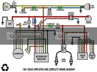
When I started what I thought could be a simple circuit mod, I found that the OEM harness had been altered and hacked at SO incorrectly SO many times I had to gut it all. I stuck largely to the diagram below, but also followed the OEM diagram at some points where the good components were already wired to OEM specs. I cannot find a diagram that uses this simplified system with a handlebar push button/kill switch for the starter, and quite frankly, I’m strongest in metal fab and moving parts and can’t elaborate or get creative with electrical. At this point I’m in a bit over my head and any help would be appreciated!!!
Notes:
*the OEM replacement solenoid I ordered has a yellow/pink and a green/pink wire where the ignition and ground should be. Which one is which?!?!
*the ignition wire from the momentary starter button is blue/white, ground black, and on the killswitch it has red/white for run and brown for off/off. This varies slightly from OEM color codes and there is no existing connector to just plug into the OEM starter button harness.
The electric start had largely been deleted except for the starter itself, which he wanted to have reconnected since his wife can’t kick it over.
When I started what I thought could be a simple circuit mod, I found that the OEM harness had been altered and hacked at SO incorrectly SO many times I had to gut it all. I stuck largely to the diagram below, but also followed the OEM diagram at some points where the good components were already wired to OEM specs. I cannot find a diagram that uses this simplified system with a handlebar push button/kill switch for the starter, and quite frankly, I’m strongest in metal fab and moving parts and can’t elaborate or get creative with electrical. At this point I’m in a bit over my head and any help would be appreciated!!!
Notes:
*the OEM replacement solenoid I ordered has a yellow/pink and a green/pink wire where the ignition and ground should be. Which one is which?!?!
*the ignition wire from the momentary starter button is blue/white, ground black, and on the killswitch it has red/white for run and brown for off/off. This varies slightly from OEM color codes and there is no existing connector to just plug into the OEM starter button harness.