Ok, a bit more pertinent info. When I got the new stator installed I realized I had put the wrong gender on the new harness yellow wire. It was a busy season and it slipped my mind til now that I never got back in there to mate them. They are currently both females and insulated. It really hasn't been a problem as I kick it to start anyway. Fixing the starter wishbone is still on my list.

But since the new stator, the yellow isn't connected.

5twins, my idle numbers match your description exactly.
 
Also, a grounded yellow wire on this stator would not have been my issue with the rectifiers. The rectifiers were all on the old stator.
 
If you measured 1.0 ohm from the battery negative cable to the grounded brush, there is a bad connection somewhere. Ideally it should be zero ohms, but perhaps 0.1 or 0.2 ohms would be acceptable.

The yellow wire coming from the stator should not go directly to ground as shown in that one diagram. It should go through a resistance such as the
Safety Relay (aka Head light Relay) coil and then to ground. The Safety Relay resistance is about 21 to 26 ohms. The yellow wire should measure around 14 volts AC with the engine idling.

Quote:
"Measuring between the stator's yellow wire and the neg batt lug, I have ~61Kohm. Looks to be a short."
I'm not understanding what this means?

The yellow wire has only 2 possibilities. It can be left open circuit if a SR is not used, or it must have a resistance as mentioned. It cannot go directly to ground, as that is a short circuit.
 
I love animations. If you watch this one, and imagine the center tap grounded, you can see how it would disturb the 3-phase output.

3-phase_flow.gif


Wait 30 minutes after watching this, before riding...
 
Ok, I've redone some checks with better accuracy. This time, with the battery removed (thanks RG), I have 0ohms on the brush ground to its terminal at the battery. All good there.

I also measure no continuity on the stator's yellow wire. One lead on its yellow wire bullet, the other on the stator housing. Seems good, although a heat-related intermittent short could be possible.

Maybe I am chasing ghosts, but the fact is my voltages are almost never at a perfect 14.1-.2. Maybe as 5twins suggests, our numbers are fine. But I hate leaving it at 'fine', especially with my in-town riding. I don't often run down the highway.

That said, she's always ready to go and if I didn't have a mounted voltmeter I'd have no indication anything is wrong. The good ol' starter test passes every time.

One question: Where would the proper black lead placement be if I were measuring voltage on the stator's yellow wire? Note, it is not as of yet connected to the harness.
 
Last edited:
I have 0ohms on the brush ground to its terminal at the battery.

I also measure 0ohms on the stator's yellow wire. One lead on its yellow wire bullet, the other on the stator housing...

Have you thought this thru?

One question: Where would the proper black lead placement be if I were measuring voltage on the stator's yellow wire? Note, it is not as of yet connected to the harness.

Voltages are a relative thing.

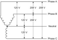
If you measure between the center tap (yellow wire) and one of the legs of the 3-phase coils, it'll be a little over half of what you'd get across a pair of coils, like this 3-phase example:

3PhaseVolts.jpg

But, the yellow wire's intended purpose is to power the safety relay, thru to chassis ground. So, put your meter's black probe on the bike's ground...
 
I love animations. If you watch this one, and imagine the center tap grounded, you can see how it would disturb the 3-phase output.

View attachment 105725

Wait 30 minutes after watching this, before riding...

I gotta stop eatin' Aunt Flo's weird marmalade......
 
Have you thought this thru?
Sorry, my meter shows 0L for infinity. Gets me every time.

Voltages are a relative thing.

If you measure between the center tap (yellow wire) and one of the legs of the 3-phase coils, it'll be a little over half of what y
But, the yellow wire's intended purpose is to power the safety relay, thru to chassis ground. So, put your meter's black probe on the bike's ground...

Right, that's what I figured. This low voltage stuff is one thing, the mixing of AC/DC is another.
 
Some more methodical fiddling around led me to finding that if the rectifier was plugged in there would be continuity between stator yellow and frame. Rectifier unplugged would remove this path.

Red lead on Yellow, Black on frame
  • w/rect 20.5MOhm
  • w/o rect ---
Black lead on Yellow, Red on frame
  • w/rect .5MOhm
  • w/o rect ---

Testing the rectifier itself, the 1st of my 'better' rectifiers, it still looks good.

Using the VOM's diode setting, everything checks out great. Voltage drops of about 400 all across in one direction, infinity in the other.

With the rectifier and battery back in line, I measured the Yellow wire voltage against frame ground.

At idle, the same 1.3-1.7vac wandering I got before.

Revved, it'll go as high as 7.x, but it's all over the place. Usually between 4 and 7v.
When it's behaving and keeping to 5-7v my mounted voltmeter shows 13.8/9vdc which is good, there's a ~.3v drop between it and battery.

Every once in a while while revving the yellow wire's voltage drops real low to 1 or 2v. At those times the mounted voltmeter drops to the low 13s.

The yellow wire should measure around 14 volts AC with the engine idling.

Confirming this. Curly's List looks for 10.5-11vac between each of the white wires. Shouldn't ~7vac or a little over half of the phase-to-phase voltage be what we're looking for?

-Still Chasing Ghosts in Phoenix
 
Last edited:
Ghostbusters.gif

... This low voltage stuff is one thing, the mixing of AC/DC is another.

AC-DC.gif

Yes, it is. DC and AC are different worlds. Take it as a learning opportunity. The way your meter measures and displays AC is important. Some meters display peak voltage, some average, some RMS. The better units display RMS. Google "root mean square voltage". And, it can get confusing. The AC voltage measured between two points can vary, depending on:

- Between 2 white wires, or white and yellow, or yellow and ground, or white and ground.
- If the rectifier is plugged in, or not. It will clip the AC peaks.
- If the rotor is receiving full power, or not.

...Every once in a while while revving the yellow wire's voltage drops real low to 1 or 2v. At those times the mounted voltmeter drops to the low 13s...

Now, THAT's significant. It implies that the alternator output may have dropped. Try duplicating that scenario, but monitor the DC voltage across the brushes. If the brush/rotor voltage doesn't change, it means one thing. If it does, it means another.

Sorry I can't help you in a direct comparison. My early alternator doesn't have the center-tapped yellow wire, and its output rating is quite less than yours...
 
Last edited:
The VOM's that we commonly use, only measure RMS AC voltage, not average and not peak.

Quote;
"At idle, the same 1.3-1.7vac wandering I got before."
I have no idea why you get that voltage reading between the yellow wire and ground. I just took some measurements.
I read 14.9 volts AC between the yellow wire and ground. I also read 7 volts DC at the same point.

Quote;
" Curly's List looks for 10.5-11vac between each of the white wires. Shouldn't ~7vac or a little over half of the phase-to-phase voltage be what we're looking for?"
Curly's voltage is a little on the low side. I measure 12.2 volts AC between any 2 white wires (phase to phase) and that is called
line voltage. There is another voltage when dealing with 3 phase power, called phase voltage, which is measuring between
the neutral point (yellow wire) and one of the white wires ( neutral to phase). I measured 7.3 volts from the yellow wire to one of the white wires.
There is a standard 3 phase formula which is:
Line Voltage = 1.732 X Phase Voltage
On my bike................12.2 = 1.732 X 7.3 (allowing for some error in measuring tolerance, my numbers are close enough)

I think you may be confusing 2 different AC voltages. There is the measurement between the yellow wire (neutral) and ground. There is the measurement between the yellow wire (neutral) and a white wire (phase voltage). They are not the same.
 
xj...................AC voltage and resistance are both useful to measure. Stator winding resistance is difficult to measure accurately because the resistance is so small, and cheap meter leads can give erroneous readings.
 
Back
Top