Stella's Overly Complicated Wiring V2

Haha, you'll enjoy this.

Here's a circuit patched into the bottom of your schematic.

Stella's Wiring Diagram-Fix02.jpg


Data sheets for the 2N3906 and 1N4148 attached.
 

Attachments

  • 1N4148.pdf
    62.1 KB · Views: 169
  • 2N3906.pdf
    307.6 KB · Views: 170
Your spec sheet for the relay shows a coil of about 100 ohms, and this lockout circuit is tuned for this 100 ohm coil. This circuit works great on my simulator.

The parts are the most common hobby items, very cheap, easily acquired. If you like, I can throw them into a bag and send them out to you. Have your electronics tech friend look this over.

D1 is a safety blocker, since we don't want any influence from the unknown headlight current sink to ground. When the headlight turns on, it feeds voltage to the transistor base, turning the transistor off, and the relay off.

D2 is a flywheel diode (catch diode), absorbs the relay's inductive kickback.

Q1 is a PNP transistor, turns on the relay.

C1 is an electrolytic capacitor. It delays the voltage from the headlight line, so that the relay has time to switch on.

R1 is a current limiter, charges C1 when headlight on. This is the lockout latch.

R2 is the trigger. When neutral opens, the base of Q1 goes high, turning it off.

Both resistors are the tiny 1/4 watt type.

Once this circuit turns off the relay, it uses virtually no current, unless the trans is in neutral, then current will flow thru D1, R1, R2, for only 1 milliamp...
 
Last edited:
Toasters in action!*

Gotta love it - don't understand it, but gotta love it!

* "Toaster" is a nickname in the engineering profession for those of the electrical persuasion.
Others include:

  • Plumbers = mechanical engineers;
  • Diggers = mining engineers;
  • Smellies = chemical engineers;
  • Muddies = civil engineers;
 
Ok, getting into the 'tuning' of the circuit really brought it together for me. I had built your prescribed circuit in a free online simulator and couldn't get it to work correctly. Either the relay coil wouldn't trip at all due to too low current, or the capacitor's time-delay on initial power-up would be too fast, or the lockout latch wouldn't engage and every time the neutral switch was closed it would drain just enough voltage for the transistor to open.

Perhaps some settings are off, I was able to find actual values for all user-adjustable variables except the inductance of the relay coil and transistor's gain.

For me, upping the value of R2 to 18k got the circuit to work correctly.

http://tinyurl.com/y8qxwong

Now that it's working and I can see what and where things are happening with the voltage and current, I can see how much fun (and frustrating) this sort of design can be. 'Tuning' indeed. It's like a sparky's version of carb jetting; change one thing and it effects every other component.

Very slick, 2M. Now, why must my circuit need an 18k R2, and yours works with 4.7k? Still chewing, but this is all rather gristly.
 
Hey, hey, well done Daniel.

You found a simulator, and got a running circuit!

And, you've acquired the grasp of how this thing works.

This circuit is a bit tricky. It has to use reverse logic, a low input turns it on, a high input turns it off. This normally requires at least 2 NPN transistors, more abundant than PNP. But can be done with a single PNP, if you understand the upside-down realm it's in. Its on/off characteristics depend on the voltage/current states between the base and emitter, same as with NPN, but occurring at the top of the transistor symbol, instead of at the bottom, where there's a reliable ground. In this circuit, the voltage/current at the emitter wanders, depending on what's going thru the relay coil. The key is to get the right values of R1 and R2 to get the base to flow, or shutoff. If the value of R2 is too high, it may not pass enuff current from Q1's base to keep the relay turned on. If the value is too low, it'll pull the divided voltage (R1/R2) too low and turn the relay on.

On my tablet, I'm using an Android app, EveryCircuit.

http://everycircuit.com

In this app, I can define various parameter values for components.

For the relay (using nominal values from your supplied spec sheet):
Coil resistance = 100 ohms
Pull-in voltage = 6v
Release voltage = 3v

For the PNP transistor (typical 2N3906):
HFE (gain) = 100 (also known as beta)

I'm using 12v for the battery voltage. Maybe could try variations from 9v to 14.5v see if the circuit works for most expected conditions.

I couldn't see any pull-in/release values for the relay in your circuit, and saw that Beta is set to 50 on your transistor. Could see if you can change those. Might then get it to work with a different R2 value.

Here, I'm demonstrating the Kettering (points) ignition on EveryCircuit.


Long ago, I bought a PC/DOS based simulator, Electronics Workbench (aka EWB). It was acquired by National Instruments, updated to run on Windows, and the last version v5.12 is available as a free download. If interested, Google "electronics workbench ewb".
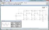
ElectronicsWorkbench.jpg

What's nice about these simulators is that sometimes you don't need to be perfect, just get a theoretical version working, then do the fine tuning while breadboarding...
 
Last edited:
Just a simple number cruncher, let's look at the relay's 6v pull-in event. And, use 12v as the supply.

Subtracting the nominal 0.6 Vf of the emitter -> base, that leaves a base-to-ground voltage of 5.4v.

6v going thru a 100 ohm coil gives 0.060 amps. (V = I * R)

The transistor's gain of 100 means that the base must flow 0.060/100 = 0.0006 amps.

0.0006 Amps over the 5.4v drop would be produced by a resistor of 5.4/0.0006 = 9000, or a 9K resistor.

That's just to barely reach the pull-in event. You'll want a bit more to ensure that it does indeed pull-in and hold. So, something a bit less than 9k should get that stronger coil pull. Try to use easily found resistor values. I chose 4.7k for R2. 10k didn't work, doesn't pass enuff current.

This is the textbook 101 analysis. But, (and there's always a but), the simulator can see things differently (extremely handy), and actual values of supplied components can vary. The nominal gain of the 2N3906 (HFE) is about 100, but I've seen variations from 60 to 300.

Your test meter may have a transistor checker, a small 4-hole plug labeled E-B-C-E, or some such. The meter will report the transistor's gain in this test. Hobbyists make use of that feature to hand select good transistors, since a $3 box of 100 will have some wildcats.

I had a batch of questionable transistors showing about 150, and adjusted my circuit to use those...
 
Last edited:
Now, let's look at the relay's 3v release event. And, use 12v as the supply.

Subtracting the nominal 0.6 Vf of the emitter -> base, that leaves a base-to-ground voltage of 8.4v.

3v going thru a 100 ohm coil gives 0.030 amps. (V = I * R)

The transistor's gain of 100 means that the base must flow 0.030/100 = 0.0003 amps.

0.0003 Amps over the 8.4v drop would be produced by a resistor of 8.4/0.0003 = 28,000, or a 28K resistor. Anything more and the relay will never hold.

Just some crunching to get another take on this...
 
Here's a slightly different version that performs better.
Stella's Wiring Diagram-Fix03.jpg


R1 was changed to a 2.7k, a bit better lockout action.
C1 was changed to a 4.7uf, to compensate for R1, and helps coil pull-in on initiation.

FYI, the 1N4148 diodes were chosen simply because they're tiny and cheap.
They can be substituted with any of the common, but slightly larger, 1N400x series...
 
To answer your question about the 18k resistor, here's a simple PNP test circuit.

The 100 ohm resistor represents the relay coil.
The 18k resistor just goes to ground, just as it would with the neutral switch grounded.
The circled "V" is a voltmeter, to show the voltage drop across the 100 ohm coil.
The PNP transistor is set with a gain of 100.
The battery is set at 12v.
PNP Test01.jpg


Turn on the simulator, observe the values.
PNP Test02.jpg


Using an 18k resistor, the voltage drop across the relay coil is 4v, current about 40ma.
This wouldn't be enuff to activate the relay.
It would need at least 7v to activate.

You can change the value of the 18k resistor to see what voltage drops can be had across the coil.

In the above post #35 circuit, the 4.7uf cap provides an instantaneous ground to the transistor's base, turning it fully 'on'. My simulator shows an instantaneous 10v drop across the coil, to really kick it into activation...
 
Last edited:
Well, the dust is starting to settle so it's time for a little catch up.

Back in December, I was getting into a pretty good place. Starting to get my feet under me with a year into a career shift, the anxiety of new parenthood was wearing off, Phoenix still had months of perfect riding weather ahead. I was feeling like Stella's rewire might get some attention and we'd get back on the road. Right...to the present.

Back on the Friday heading into Labor Day weekend my wife sends me a text telling me she was offered a job halfway across the country where her brother and his family live. We'd been living in Phoenix for the work network, but neither of us had deep roots there and moving would allow our toddler to grow up with a handful of cousins. Grandma and Grandpa wouldn't be too far either. So by Saturday the decision was made to move back to the green part of the map and on Tuesday I gave my two weeks.

Now, about the bike. I hated to move her again without fixing her first. We had made a forced in-town move six months before and the indignity of having to trailer Stella still rankled. Wife says I should make it happen. She was headed to St. Louis the next week to find us a house and was taking the kid with her. I could spend my last week working by enjoying uninhibited evening hours in the garage. Excellent!

After a frenzied week of pizza and wiring, I got it done. Final ground terminals were made just before picking up wife and kid from the airport. When I got back to the house I did a quick test. She charged, started, advanced. Head light, tail light, runners all worked. But, the hazards didn't work and the turn signals let out a little smoke from the left switch. Oh, well. Figure it out later, truck to pack.

20190921_174711.jpg


Don't worry, she got out safely.

Somewhere in the desert between the Grand Canyon and Arches, it hit me. I had confused the R/Y wire with the Y/R. One would supply 12V to my hazards relay where I wanted it. The other would send 12V straight to ground when a turn signal was engaged.

Found myself twenty minutes in the storm of moving in. Popped the headlight out, made a quick swap, all buttoned up. Hazards and turns are a go.

All I need now are a couple quarts of oil.

More pics and detail to come, but here's a sneak peek. Suck it in, Stella.

20191007_113421.jpg
 
Hi Daniel: it’s so nice to hear from you and learn about your great news! Congrats on sorting out Stella - she really is a beaut.

I’ll bet your little chap is really starting to move and groove these days. My late Mom (a pediatric nurse) always used to call the two year old age “the NO stage” because more often than not, the response to any parental request is NO!

Anyhow, all the best for a safe and fun move and please check back into the forum when you settle down on the green part again.

Kind regards,

Pete
 
Last edited:
Back
Top