Tuning.....Where the hek to start!

Paul75

XS650 Addict
Messages
259
Reaction score
185
Points
43
Location
UK
So the street tracker is looking good but now comes the hard part (for me anyway). Its a '79 special with stock carbs and K&N's. Finally got it running, but sounds rough. Occasional backfire and I think misfire but also a loud pop coming out of the back of the
air filters, the pop is pretty hard and feels like its banging up against the metal rear of the filters.....what is that??

Both new plugs are wet oil fouled. Carbs are clean but probably not jetted right for short upturned exhaust end cans!!!!

Where should I start? I know I'll ditch the K&N's for the foam type to ensure even airflow.....any advice really appreciated as always....
 
There is an order to tune ups.
This list starts with the mechanical, hen electrical then on to the carbs.
#1 Adjust can chain tension
#2 Adjust valve clearance
#3 Adjust points gap
#4 Adjust ignition timing
These 4 things take care of the mechanical and electrical.
Now on to the carbs. www.amckayltd.com/carbguide.pdf is our carb bible. Use it to correctly tear down, clean, inspect, replace worn parts then reassemble, adjusting things as you go.
Once you get the carbs clean you use the "Tuning For Mods" section to test the set up you have. Use the results from your testing to determine what you need to change.
Make ONE change at a time, test, one change test. This is the only way to get the carbs right. There is no magic formula.
With what you say you have done to the bike I would start out with one size up on the pilots and two sizes up on the mains.
This should give you a good place to start.
On the Pods, change to the foam before you start tuning.
Leo
 
Almost forgot, your repair manual has all the specs and how to's on the tune up steps.
Leo
 
Yes, ditch the K&Ns. They won't allow you to run a large enough main jet without break-up in the upper midrange. That makes you think you're as big on the mains as you can go, but it's not the jet size causing it, it's the turbulent air flow through the K&Ns.
 
Brilliant info.....going to be busy over winter!

Paul - are you running an electronic ignition?

There are two for the XS650 - the Boyer-Bransden (B-B) and the PAMCO. Both are well regarded and have their advocates. The PAMCO seems to be more common in North America and I think the B-B is made in the UK. These units are basically set and forget and a key advantage is that they can drive a higher voltage ignition coil and IMO, remove at least one variable on the tuning front.

Earlier units required you to retain the stock ignition advance mechanism (which lives inside the RH end of the cam housing under the circular chrome cover) but PAMCO Pete just released a brand new unit (less than $200 USD) with a built-in timing advance capability that looks very slick. There was an intermediate “Mk-II” version of the PAMCO that had an electronic e-advancer which eliminated the mechanical timing advance unit and used electronics in a separate little box but it required you to run more wiring and find a secure place to mount the box. The latest unit (just released last week) eliminates the separate box and looks really easy to install.

Anyhow - onward & upward!!

Pete
 
Last edited:
"These 4 things take care of the mechanical and electrical."

Not unless it's sporting new plugs, plug wires, & the coils & overall wiring are good.

New plug caps too. Strange how the red ones are easy to get and the black ones hard to get in the UK, in the US it is the other way, easy black and hard to get red.

Scott
 
... got it running, but sounds rough. Occasional backfire and I think misfire but also a loud pop coming out of the back of the air filters, the pop is pretty hard and feels like its banging up against the metal rear of the filters.....what is that??

Both new plugs are wet oil fouled...

I see from your other posts and pics that you're running the OEM ignition, points to 2 coils.

There *is* a scenario that can lead to poor ignition and backfire.

When a points "close", that cylinder is approaching BDC, and the intake valve is nearing its closure.

*IF* the points are dirty, pitted, or whatever that makes an intermittant grounding connection, the coil may spark during this closure event.

And, if there's sufficient unburned fuel hovering about the spark plug, it *could* ignite.

With the intake valve still slightly open, that's the only escape path for the combustion.

Food for thought...
 
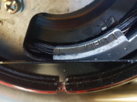
Update....so I've adjusted the cam chain and am onto adjusting the valve clearances. Could someone tell me if this marking is top dead centre please, or do I need to be to the left of the T marking?....

20171210_122313.jpg

Just ordered metric feeler gauges on Amazon prime so will have tomorrow.

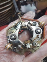
I've taken a look at the points....do these look ok?
20171210_113240.jpg

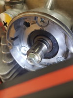
One thing I did notice is this part looks worn to me, it's oval not round.....it this normal? If not what is it called and I'll order another....
20171210_113734.jpg
 
On another note I found this video on youtube BUT surely this is not correct, this is not actually adjusting anything??

 
Hi Paul: please forgive me if I am incorrect but it’s beginning to to sound as though you are doing this without a manual and that is risky. I’m sure that everyone else here will join me in strongly recommending that you get a manual and read it carefully before proceeding. Several manuals are available including at least one that is a free download.

To respond to your specific questions above:

1) I can’t make out which timing mark you’re referring to but the manual will clearly explain which is which;

2) I doubt that anyone can say for sure if those points are good just from a photo. There are several critical characteristics including the wear of the cam pad, the stiffness of the springs and of course the condition of the little breaker contact points themselves (they should to be smooth, flat, parallel and clean for proper function). In your photo, the contact points are closed so we cannot see the contact surfaces.

The other thing I noted is that several of the little adjusting screws have damaged heads. That is very common and it indicates that they’ve been in service for a while and that someone has likely been in there with the incorrect Philips screwdriver. Everything on a Japanese bike or car that looks like a Philips screw - isn’t. It is actually a JIS (Japan Indstrial Standard) screw and requires a proper JIS driver. These are readily available on Amazon as a set for around $50. The best brand is “Vessel” and they’re a distinctive blue-geeen colour.

Breaker points are not expensive so if in doubt, I’d replace them or consider going to an electronic system which eliminates them altogether, as noted in my earlier post.

3) That out-of-round part is the points actuator cam. As it rotates, the eccentric profile pushes on the points actuator pad and that causes the points to open and close at the correct time. So - you are correct that it is not round and that is exactly as it should be.

On the valve adjustment video: yup, I don’t like that one at all. The statement about ignoring the timing marks and just trying increasingly thick gauges may actually work to check the clearance, but it doesn’t cover an adjustment and that is critical. It is therefore inefficient and IMO, requires a bit of finesse that many people may not have. Also, as you say, he didn’t seem to get to the part where the actual adjustment took place.

Finally, a general word on valve adjustments: always err on the side of a slightly larger valve clearance. While an engine with a smaller clearance might run more quietly, the risk of a valve not fully closing is significant and that usually leads to a burned valve seat which requires a big engine repair.

Most experienced mechanics agree that “Looser valves are happier valves”.

Stick at it my friend - you’ll get there.

Pete
 
Last edited:
Pete thank you.....good advice. I do have the full original workshop manual so I have access to the valve clearance tolarance measurements so will sble to check them accuratly once the feeler gauge arrives, ill take your advice and edge on the looser side.....

I now know the timing mark is to the right of the T. I will take out the points cam later and clean it up a little......
 
Hmmmmm.....clean it up....

OK - BUT - do not sand, grind or otherwise molest the outside eccentric profile of the cam. The correct timing of the spark depends on the shape of that cam. Frankly, I’d just leave it in place and simply give it a wipe with a clean rag soaked in some engine cleaner.

Also, when you reinstall the points, those little felt pads on the points assemblies need to be impregnated with the correct lubricant to prevent excessive wear on the cam and cam actuator pads.

Have you got some authentic JIS screwdrivers? If not, I’d order a set of a #1, a #2 and a silver handle #3 Impacta impact driver (extremely handy for clutch screws). If you use a Philips driver on JIS screws, you risk damaging or even stripping the heads (as has already been done on some of the screws in your photo).

Pete
 
You might consider replacing the JIS screws with Allen/hex/socket head screws. IME the smaller shaft of the hex key makes it easier to access and gives a better "grip". You can find replacements for the tiny screws used to hold the petcocks faceplate to the larger ones used to hold the lower rear mudguard. Just takes a bit of searching.
 
Ok will leave the cam in place. Will check manual for correct lubricant for the pads and totally agree about the correct JIS screwdrivers.....will be ordering those right now!
 
You might consider replacing the JIS screws with Allen/hex/socket head screws. IME the smaller shaft of the hex key makes it easier to access and gives a better "grip". You can find replacements for the tiny screws used to hold the petcocks faceplate to the larger ones used to hold the lower rear mudguard. Just takes a bit of searching.

I will replace these because 2 of the heads are damaged. Just ordered a pack of 30 stainless button heads for only £1.75.....good old ebay!

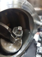
Now, the top of this tappet has a 4mm male square, are people using a dedicated tool for this or just a 4mm spanner?

20171210_153928.jpg
 
I mentioned in a thread somewhere that you can just drill a 4mm hole in a piece of steel and file it square for the tappets. But, if you replace the tappet/lash screws with slotted head or Allen key then the adjustment process is so much more controlled than with those original 4mm squares.
 
Back
Top