Unnecessary electrical components

Link94

XS650 Enthusiast
Messages
41
Reaction score
30
Points
18
Location
Walla Walla WA
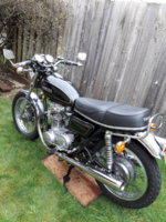
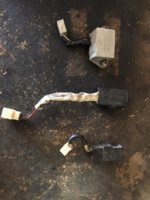
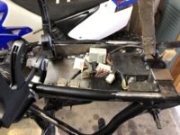
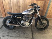
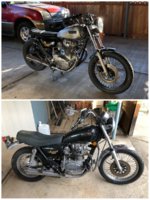
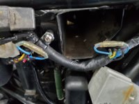
Hi guys I’m new to the site so bear with me here. Last year I pulled a 1980 XS650G out of my Grandpa’s barn and spent the winter restoring it. The thing fired right up after new filters fluids and a battery! I put 1000 miles on it this year and decided I wasn’t satisfied with the build and took it down to a frame last week. My question today is about wiring, I would like to minimize the wiring in my harness and have built an electrical tray to hopefully house the components along with a new smaller battery. There are three components in the harness that I am not sure of their purpose. I was hoping someone could tell me if they were necessary to keep in the harness or if I could rip em out and make my life easier. I’ll put a picture of the three components in the post. I appreciate any help or feedback.
 

Attachments

  • 20A8DDA6-43A3-43E2-9D20-36707B4E1334.jpeg
    20A8DDA6-43A3-43E2-9D20-36707B4E1334.jpeg
    217.5 KB · Views: 170
  • 992FCDF0-36C6-4577-8753-050F0154B27F.jpeg
    992FCDF0-36C6-4577-8753-050F0154B27F.jpeg
    184.9 KB · Views: 169
  • A2606380-25AC-474B-84E5-1B959AEC2409.jpeg
    A2606380-25AC-474B-84E5-1B959AEC2409.jpeg
    230.2 KB · Views: 185
  • 590C3572-DE4C-46E7-A455-767E4F77C485.jpeg
    590C3572-DE4C-46E7-A455-767E4F77C485.jpeg
    241.4 KB · Views: 182
20200316_142116.jpg

Two of those, the "light checker" and the "Reserve Lighting Unit" can be removed and each require a jumper on one wire only. (On my 79) Blu/Yel to Blu & Blu/Yel to Blu/Blk. Left to Right in the pic.
Find a 1980 wiring schematic to confirm.
Hey, from WA state !
-R
 

Attachments

  • 20200316_142134.jpg
    20200316_142134.jpg
    136.6 KB · Views: 120
All 3 of those components can be removed.
... and welcome to the forum. :D Used to go visit a buddy in Walla Walla when I was stationed in Mt. Home Id.

Untitled.png
 
Awesome thanks for the info guys they didn’t look super vital to the hauling ass capabilities of this old bike but I figured I would ask the pros. I’ll confirm with a wiring diagram.
 
I would say just add in the jumper wire and leave the rest of it alone.
 
The power feed for the headlight passes through the RLU. The power feed for the tail light passes through the light checker. Remove those components and you cut the power to those items. You need to add a jumper wire to restore the power flow.
 
By chance do you ever see this 78XS over in WallaWalla?
 

Attachments

  • 20190822_162647_IMG_1617.JPG
    20190822_162647_IMG_1617.JPG
    326.7 KB · Views: 102
It's over there close by. Supposedly a small vintage group of riders over there. I like riding in the Columbia Gorge and intend to ride up your way this spring.
-R
 
Very cool I hope to have mine back on the road in the next month or so depending on how much time life gives me to work on it
 
Hey guys so I did the above mod to my electrics but didn’t pull the connectors off completely and sauter the ends like machine did and now every time I turn my key my 20A main fuse blows. I just got done routing all the wiring where I want it to be but that is the only thing I have changed on the stock harness. What do you guys think my problem is?
 
I just pulled the two applicable wires on both connectors and jumped them and left the rest intact in the connector.
 
Hi, just read your thread. I'm interested because, to cut a long story short, my 1978 XS had modified/butchered wiring and for me it seemed the easiest option was to take the whole lot out and build a minimal one-off wiring system. Getting rid of those three items plus anything else I couldn't see any use for has left the bike with simpler wiring, a lot less cable running all over the place and a system I can just about understand. People who have read my thread are aware of the limitations of my understanding . . .

So instead of slimming down, leaving components on the bike isolated by a jump wire, I took the opposite approach. Pulled everything out, taking notes as I did, then started with new tracer cable, a pile of bullet connectors and a crimping tool and built up only what was needed.

If you are interested in the long story, its all there at http://www.xs650.com/threads/miss-november-xs2-tribute.55057/

Here's the wiring system, prior to recent minor changes for a different alternator. There will be differences from yours such as Boyer ignition.


PICT2139.JPG


If you are tempted to do something similar, don't be afraid to take the plunge - there's plenty of knowledgeable people on this forum who have always been very helpful. And you will have a system you know inside out.
 
Thanks for the info I’m stumped at the moment every time I turn the key my main fuse blows and with the key turned off I only have power to the red wire in the ignition. Everything worked great before doing the above modification so I’m thinking about just putting it all back the way it was. Or pulling all the electrical tape off the harness and really getting to the bottom of it because I’d like to not have those components.
 
If you pull all the electrical tape off the harness and really get to the bottom of it then you will probably end up doing what I did. So best not to read on.

Took a sketch pad, pulled the harness apart one wire at a time, noted what it connected to at both ends, drew little diagrams of the wiring going to each switch/component. Read Leo’s simple guide to XS650 electrical system, came to realise the electrics are not really very complex. Then Jim pointed out where there are some wiring diagrams in the Tech section. My XS's wiring is based on one of those, modified for the Boyer ignition. The little numbers on the diagram are inherited from those first explorations. Spent about £40 to buy tracer wire, 3.9 mm Japanese bullet connectors and sockets, a few ring terminals, etcetera. The bike now has wiring which is completely new and far simpler. Just removing the flash cancel unit or the light checker means a very big reduction in the wiring needed. So my XS just has the things it needs - charging circuit, ignition, lights, brake lights, horn, indicators. But most important I know what is there and mostly understand it.
 
I would check the jumper wires you installed. Make sure they're going to the correct wires and that they are not touching any others. Here's the jumper wire I make up and use for the RLU. Notice how I totally insulate the ends so they won't contact anything else but the intended pins in the connector .....

ITGmYKY.jpg


KcTBN8X.jpg


FvJKZ77.jpg
 
That’s a good idea I actually removed the connector completely which I wish I wouldn’t have now and done it that way but this works too. I made sure the connection was good and soldered the ends of the other wires.
 
Back
Top