Well that didn't last long!

gggGary, when I installed the rewound rotor the sanding was quite coarse - perhaps 180 - 240 Grit. I smoothed it off with 600 Grit and then polished with Autosol. I wonder if the wax in the Autosol was the problem?? Your mention of minerals spirits may be the answer to remove all traces of wax. I will do a 10 mile test ride as is and if all is well it will be new brushes and polished rings.

Thanks for the tip.

Note: Carbon brushes do not work in a vacuum according to a NASA documentary I saw in 1974. The brush needs oxygen absorbed at the interface.
 
Now i am confused. Readings on the crankshaft and reading off. Anyone ever see this?? Yes had probes on one screw and on the other. I guess my initial reading on the bike was at 1ohm. Not real sure what to make of this one now.
20180527_090944.jpg
20180524_184234.jpg
 
Lets see pic of the side of the rotor. Yes a low reading like that means the rotor windings have shorted out internally essentially bypassing most of the wire coil, IE game over for that rotor. Very dark or black bubbly varnish on the windings will confirm the rotor has overheated and the varnish melted, letting the wires short out. A typical result of some know nothing continuing to run with a bad battery, the rotor dies trying to charge the unchargeable.
 
Sorry for the confusion. When checking a rotor resistance you measure as in your top or middle photo. What I am suggesting is to examine the brush/copper ring interface. That I did as shown in your bottom photo. The value you get here will be a sum of the brush resistances and the rotor. I would expect it to be about 5.5 - 6 Ohms if the rotor is good. In my case I was getting 14 Ohm so something was messing up the contact between the brushes and the copper. Light sanding hopefully solved this.
Screw.jpg
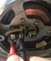
This is me making the measurement. The screws are convenient to use because the probes will not slip out of the slots.
 
In your bottom photo is that a 2.4 Ohm or a 24 Ohm. If 24 Ohms then you may have a similar scenario to me.
 
My OEM rotor was not like that but my rewound rotor does have fiber glass tape wrapped around it and then covered in epoxy.
 
gggGary have you seen an oem rotor with cloth over the windings like that? New to me.
I noticed that also, the import rotor I have looks just like that!
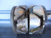
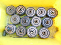
some examples of new and (well, ill) used rotors.
Note the variety of ohm readings on the tub full of rotors.
REALLY bad original on left, new aftermarket on right.
rotors (1).JPG
variety of side views some like new, others like a frying pan left on the stove.
rotors (3).JPG
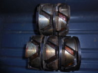
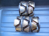
more sideviews
rotors (4).JPG
tub full of various rotors, note ohm markings. This tub is the remains from my swapping in and selling good rotors.
rotors (2).JPG
 
Last edited:
So there may have been an issue with the copper/brush interface being contaminated. It may be that you have a loose or poor contact on your meter. Be careful when touching the copper rings, if you press the probes hard they will leave indents that can damage the brushes. I place the probes as flat as possible then I can push harder to get a consistent reading without damaging the copper. Also by using the outer part of the ring you avoid damaging the area where the brush runs.
 
4.7 is low useable.
factoid. the rotors tend to not fail "all at once" they will get one short in the winding. this INCREASES the amount or current going through the rotor. it now gets HOTTER, more shorts are inevitable, run it long enough and you will eventually see a 1 ohm reading, if the solder on the connections doesn't melt and it goes open circuit first. I can't prove this but pretty sure that's typical "death of a rotor"
 
Back
Top