Why isn't this flasher working

ckahleer

XS650 Addict
Messages
173
Reaction score
272
Points
63
Location
Glen Allen, VA
My 81 Special2 did not have turn signals when I bought it. I put on a set of LED signals and they work well ,as long as I use resistors.
Not wanting to use resistors, I purchased this electronic flasher. Turn signals do not light at all with this new flasher installed. Any Ideas why this flasher does not work?
The smaller flasher is the new one.
 

Attachments

  • flasher.jpg
    flasher.jpg
    81.6 KB · Views: 101
Probably has to be wired differently. I had to wire my led flasher the way it shows on the side which was different then the stock wire connector. I am not running resistors for my led turn signals. I did have to take out the turn signal indicator filament bulb for mine to flash though.
 
My 81 Special2 did not have turn signals when I bought it. I put on a set of LED signals and they work well ,as long as I use resistors.
Not wanting to use resistors, I purchased this electronic flasher. Turn signals do not light at all with this new flasher installed. Any Ideas why this flasher does not work?
The smaller flasher is the new one.
I had to do a modification to the wiring on my 83 Heritage Special when I switched over to LED. I don’t know if your bike is the same. Basically it has to do with the way the turn signal indicator is wired in. It has been a long time, but I did write it down on a piece of paper somewhere. I will take a look. Why would you need resistors for this change?
 
Nope. I can’t find my notes. Bushyeyed is right. Pull the turn signal indicator. Basically the indicator is lit up by the plus voltage signals from both sides, DG wire for the right, CH for the left. When one is high the other is low allowing current flow through the indicator from one side . Current flow is from the other direction when the signal is switched. It’s a cheap and dirty way of doing it. When I changed mine over I also put a LED indicator in. It involved some rewiring in the headlight rats-nest.
 
On the stock system the power cokes to the flasher on the brown wire, out to the turn switch on the brown/white wire. The other wires are used by the self canceler.
On the older bikes with a stock 3 prong flasher, 3 prong flashers from the parts store won't work. On 4 prong flashers I have read the same thing.
It may be possible to rewire your bike to use one of these flashers. I don't know how myself.
I do know that you can use a 2 prong flasher and they work well. The one drawback is the self canceler won't work. Noit a real problem, just have to remember to turn them off manually.
I use flasher from Super Bright LED's. Item # LF1-S- FLAT. It comes with wire leads coming out to a plastic plug block. The wires can be removed from the plug block. This leaves you with blades on the wires that plug into the stock plug block. On the plug block you will see where the brown wire is, plug the red wire in where the brown wire is, plug the black wire in where the brown/white wire is. Some of the flashers may come with a grey wire instead of a red wire. Just plug that in the brown.
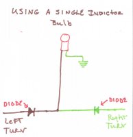
On the later bikes they used a single indicator bulb. This bulb has one lead hooked to the right, one to the left. As the turns flash the bulb draws power from one side and grounds through the other.
When you convert to LED's this set up cross feeds and makes both left and right to flash at the same time. Unplugging the indicator bulb lets them work fine. Most like the indicator light. To make it work right you need to do a bit of a rewire on the indicator. Trace the wires down into the headlight bucket. Unplug them. Build jumper wires that plug in harness side plug.. On each wire from the plug you hook in a diode. One the other end of the diodes you hook them together with a bit of wire. Hook this wire into the indicator wire plug. The other wire in the plug run a wire to ground.
I have a wiring diagram I'll post up.
Leo
 

Attachments

  • Diodes for turn signals 001.jpg
    Diodes for turn signals 001.jpg
    72.2 KB · Views: 75
Back
Top