Wiring diagram for separate regulator/rectifier.

PickleSlice

XS650 Addict
Messages
152
Reaction score
5
Points
18
Location
Lakeland, FL
I've visited the tech section and seen all of the wiring diagrams, but none seem to fit my application.

My setup is this:

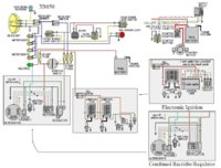
Stock alternator, VR115 regulator and 3 phase 30A rectifier, headlight, tailight, ignition switch, kill switch, and no turn signals, kick only.

I also purchased one of the wiring harnesses that DADDYGCYCLES sells, http://www.xs650.com/forum/showthread.php?t=41750.

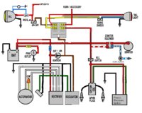
I also really like the diagram that DADDTGCYCLES posted in his thread. I can omit the turn signal circuit, but I have no idea how to wire up a separate regulator/rectifier setup.

Here's the diagram that was posted in the harness thread - View attachment 55040

Edit;

I also want to add that it is a basket case and none of the factory wiring was working correctly, so I've pulled the stock harness out.
 
Scroll down the post listed belowand there will be one by Skull that has stock diagrams. They look about postage stamp size but get larger when you click them. They are all right out of the box Yamaha diagrams and will give you an idea of how to hook up the separate regulator and rectifier combination. There are diagrams for pretty much every year of XS.

http://www.xs650.com/forum/showthread.php?t=61
 
Here is how you do it with the diagram. Do you have the stock harness?
If you have the stock harness and the separate REG/REC you can send it to me and I will break it down and send it back done. You just pay shipping both ways.
 

Attachments

  • 650 wires.jpg
    650 wires.jpg
    94.1 KB · Views: 4,612
Here is how you do it with the diagram. Do you have the stock harness?
If you have the stock harness and the separate REG/REC you can send it to me and I will break it down and send it back done. You just pay shipping both ways.
I will keep that in mind, thank you much!
Here is another
That looks great! I don't have a starter, but I'll just omit that circuit.

My only question is, how do I know what wire on the rectifier goes to what wire on the alternator?
 
Maybe I'm not understanding the question but the diagram is on the side of rectifier.
The 3 wires from the alternator goes go to the side with 3 spades. One wire per doesn't matter which one of the three.
Looking at it from the side with the 2 posts closest to you ground is on the left and positive is on the right.
 
Nomad if you need harness PM me of what you have or going to use and I can give you a price. My harnesses comes with switches fuse box and all the wires needed.
Just have to know what you are running POINTS TCI PAMCO BOYER.
Thanks Rich
 
I have this older separate rectifier but my problem is it has no wires hooked up to it at all i have the wires i just need a image of what wire goes where so I can hook this thing up if somebody can post a pic it would be a huge help thanks
 

Attachments

  • Screenshot_2017-10-22-20-58-10-1.png
    Screenshot_2017-10-22-20-58-10-1.png
    98.3 KB · Views: 390
The wiring diagram shows it clearly. The red wire connects to the upstream side of the ignition switch, which is the same place where the 20 amp fuse, coming from the battery, connects. The black wire connects to bare metal on the frame (not the battery box), or to a common black ground wire that runs in the wiring harness. Very simple.
 
But normally, you don't solder the unit into the harness, you use a multi pin plug. That way you can easily disconnect it if it needs replacing.
 
Back
Top