Wiring from scratch, judge my diagram!

timeconsuming

In Nonsense Is Strength
Messages
54
Reaction score
0
Points
6
Location
San Diego
Hey guys

Here's a few notes on my bike to start with:
-1979 xs650
-PAMCO installed
-stock stator/alternator/reg-rec
-LED taillight
-single filament headlight
-xs performance coil
-stock size battery (12v 14ah?)

Anyway, I'm rewiring my bike (first time rewiring a bike from scratch) and trying to keep things simple but just want to get some opinions on what I've come up with.

Basically I tore the whole wiring harness out and went about simplifying as much as I could while still maintaining a few key functions (brake switches, tach light, etc).

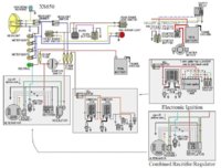
I went off of this guy, as it had the same reg/rec-stator/alternator wires as my current (what I believe is stock) setup:

index.php


And then a simplified chopper setup with a PMA and a PAMCO:

simplifiedwiring.jpg


I also used the diagram in my Haynes manual... and ended up with this as my design:

xs650-wiring-diagram-1.jpg


Any obvious flaws or recommendations for improvement?

Thanks!
 
Firstly I am not a bike wiring pro and no nothing about Pamco ignition wiring however I can see the following for you to consider:

1. The ignition is unswitched straight off the battery it will be permanently energised.

2. There is no fuse in the ignition sub circuit- so you have no short circuit protection.

3. The headlight switch does not control the taillight- it will run (burn) when the key switch is closed.

4. The alternator rotor in your picture is a wound rotor type that will not work with your diagram, if you are using a permanent magnet alternator (PMA) then the diagram looks ok.

5. It is good practise to place protective devices (fuses, circuit breakers) as close to the power source as possible so that as much of the sub circuit wiring is protected as pracitable. You may intend to do this but it is hard to tell from you diagram.

I am mindful of that there may be other things that I have not seen and that you may have intended the ignition and tail light to operate as described. I hope this is helpful.
 
3. The headlight switch does not control the taillight- it will run (burn) when the key switch is closed.

4. The alternator rotor in your picture is a wound rotor type that will not work with your diagram, if you are using a permanent magnet alternator (PMA) then the diagram looks ok.

3. Including the instrument bulb.

4. There's (2) stock alternator/rotor setups, early model has regulated-power going to grounded rotor, late models have power going to ground-regulated rotor. Your wiring, rotor brush configuration, and regulator must match.
 
First of all thanks for the input! I am further from a wiring pro than anyone I think, so it's nice to have some light shed on my doubts.

Any further explanation would be appreciated, I want to make sure I understand what points you've made:


Firstly I am not a bike wiring pro and no nothing about Pamco ignition wiring however I can see the following for you to consider:

1. The ignition is unswitched straight off the battery it will be permanently energised.

I think I see what you mean, I have the PAMCO and Coil running directly to the battery... should I have it wired to the Brown wire from the coil rather than the red?

2. There is no fuse in the ignition sub circuit- so you have no short circuit protection.

I'm not sure I understand this part... I haven't seen any other diagrams with fuses between the ignition and the coil, would running the coil through the brown wire, which has a fuse before the key switch, solve this?

3. The headlight switch does not control the taillight- it will run (burn) when the key switch is closed.

My thought was to have the tail light on when the key is turned, as my tail light is an LED with minimal draw on the battery. I wanted the ability to ride the bike with the tail light running and not the headlight. Are you suggesting that with the current wiring I laid out, it will always be on even with the key in the off position?

If I were to run both the tail and headlight to the on/off switch, I assume the brake light would still function even when it was in the off position so that would be an option? My thought was to always have the running light on, sort of as a battery level indicator when I turned the key before kicking over the bike.


4. The alternator rotor in your picture is a wound rotor type that will not work with your diagram, if you are using a permanent magnet alternator (PMA) then the diagram looks ok.

I'm not completely certain what type of alternator I have, though I believe it to be stock for a 1979 xs650 engine, definitely not a PMA (though I intend on eventually getting one of those. The wires coming out of my alternator match the colors of the first diagram I posted, so I went off of that, rather than the PMA diagram (the 2nd one). What is it about my diagram with the alternator pictured that won't work?

5. It is good practise to place protective devices (fuses, circuit breakers) as close to the power source as possible so that as much of the sub circuit wiring is protected as pracitable. You may intend to do this but it is hard to tell from you diagram.

That is a good point, I mainly just put them up by the key to keep it simple. Any recommendations as to where better to locate them? I assume nearest to the battery, lights or ignition?

I am mindful of that there may be other things that I have not seen and that you may have intended the ignition and tail light to operate as described. I hope this is helpful.

Can't thank you enough!

3. Including the instrument bulb.

Any recommendation for how to better wire in the tach bulb? I sort of just assumed it needed the same power source as the other lights... I'm pretty new to this stuff haha

4. There's (2) stock alternator/rotor setups, early model has regulated-power going to grounded rotor, late models have power going to ground-regulated rotor. Your wiring, rotor brush configuration, and regulator must match.

I'm assuming a '79 would be a later model but I'm not positive on that... I sort of just grabbed a photo from google image searching 'xs650 rotor'... Anyone care to shed light on which setup I should have? Like I said, the wiring colors match that of the first example diagram I posted.

Thanks again!
 
Time consuming here we go:
This is how I think about wiring
The start of a circuit is the battery, or fuse, the end is the earth. Power runs from the battery through the fuse to a switch. If the switch is closed (on) the power continues on to the load (light for example). It passes through the load and onto earth (ground) back to the battery.

If the switch is open (off) power travels to that point (the switch) and can't continue so the light does not run (burn).

To sort items 1 and 2 in one go;

Remove the red wire feeding the ignition (shown going to your ignition coil) and connect it to the brown wire from your ignition switch. Following the circuit through, power will run from the battery through the 30A main fuse to the ignition switch. When the switch is closed power will flow through the 10A fuse to the ignition, charging system and the stop light switches.
You will have a fuse and a switch in the circuits.

Item 3 Part 1
As drawn your tail and instrument lights will only run when your ignition switch is closed. So the tail light is as you wanted. If you want the instruments to only be on with the headlight, connect them to the headlight side of your headlight switch.
Part 2
As drawn the brake light circuit is independent of the headlight circuit. Both will only be energised when the ignition switch is closed. I am not sure of your terminology as to what a running light is, but if you want a better indication of battery condition use the headlight it is a reasonable load and will be dim if the battery is low. A small lamp doesn't load the battery enough to test it.

Item 4
Sorry my mistake you may be correct but you will need to positively identify what type of alternator you have. Then wire to suit as Two Many XS's suggests. Comparing your wiring to a workshop manual will help and a photo of your set up would be useful to someone who knows. I have no experience with stock charging systems.

Item 5
In the top diagram, the 30A main fuse is straight off the battery (a good idea).Wires to and from the battery will be protected. In practise all your fuses will probably be in the same place it is how you connect them. In your diagram the blue and brown wires from the ignition switch will be protected by the 30A fuse on the run from the ignition switch to the 10A fuses.

Draw another diagram incorporating the changes you want to make and we can take it from there.
 
Thanks for the breakdown! Sorry if my terminology got a bit weird, I blame my novice level.

I'll do a redraw and come back for more! Thanks.
 
I have chopped your drawing about a bit. It should work as you want apart from the charging system which needs to be confirmed.
 

Attachments

  • wiring (800x582).jpg
    wiring (800x582).jpg
    197.1 KB · Views: 665
Lately I've seen several references to 30 amp main fuses. I'm not sure where this is coming from. The 650 originally had a 20 amp main fuse. A 30 isn't going to pop as readily as a 20 and I'm not sure I'd want that.

Pamcopete recommends fusing the Pamco using a 7.5 amp fuse. But actually, he instructs you to fuse the power line into the coil, not the one into the Pamco. Apparently if the coil goes bad or shorts out, it can take the Pamco with it.
 
Just to throw in my two cents, Diagram #1 is fine except the 30 amp fuse. Diagram #2 is ok.
Diagram #3 has a few glitches. Signal fixed some. I would run the red wire from the reg/rec straight to the battery. Put the 20 amp, not 30 amp fuse between the battery/reg./rec and the rest of the wiring.
If you look at the rotor you can see it's a later rotor, it has the magnet for the TCI. So it can work just fine. Even if he is using the stock 79 rotor it can work just needs the three nylon screw mod.
I would also use a 7.5 amp fuse in the line for the ignition. I have my 7.5 feeding both the Pamco And coil. If the fuse blows all power to the ignition stops.
Other than those few things it will work.
leo
 
Thanks guys, all makes sense, kicking myself for not seeing it before.

I plan on popping off the dry side cover over the alternator and snapping a picture to post up just to be sure before I go about measuring and buying wire.
 
Just one more thing, diagram #2 uses a PMA. You are using the stock FEA. or Field Excited Alternator.
So that one won't work for you.
I like this diagram. It has the basic points ignition and reg and rec. The later TCI and combo reg/rec are in boxes. Just swap around the boxes to match what you have. If you run a Pamco just wire it in after the engine stop switch, Kill switch to most.
If you want the E-start, it's in the upper right.
If you want turns just add a fuse run the wires, switch and lights.
Easy to mod for PMA.
Leo
 

Attachments

  • 314w9s3.jpg
    314w9s3.jpg
    135.4 KB · Views: 1,244
Alright.

So here's the wires coming out of the alternator (including the yellow wire [safety relay?] and the sky blue [neutral switch?] coming to a total of 7 wires):

IMG_2960.jpg


Here's the view with the cover off:

IMG_3030.jpg


And here's a more up close shot of what I assume is the brush assembly:

IMG_3031.jpg


Hopefully that sheds some light as to what I've got in my bike.
 
I Don't see the 7.5 amp due for the Pamco. Really cool how you do these drawings for sure, wish I had the ability as I need to make an entire new harness from scratch also.
 
I was wondering about that. Would it be on the brown wire right out of the coil?

I take it the 10 amp on the brown wire isn't enough then?

EDIT: or is it that it needs a fuse between the Alternator and the coil/pamco ?
 
I'm not positive but I have seen it on your tan wire out of the coil which is red on many of the other diagrams, from what it sounds like as the the guys mention below here, from the above posts. SO I think on your tan to coil is correct but you read and check it out too.

Here is what 5twins said Pamcopete recommends fusing the Pamco using a 7.5 amp fuse. But actually, he instructs you to fuse the power line into the coil, not the one into the Pamco. Apparently if the coil goes bad or shorts out, it can take the Pamco with it.

And what xsleo said I would also use a 7.5 amp fuse in the line for the ignition. I have my 7.5 feeding both the Pamco And coil. If the fuse blows all power to the ignition stops.
 
You may want to take the rear brake light and and brake switches off the ignition circuit and move them over to exist with your other lighting circuit and have a dedicated ignition circuit then you can have the 7.5 and nothing else in line with it to ever confuse an ignition problem caused by a brake component.
 
Back
Top