Wiring from Scratch

figure8

XS650 Guru
Messages
2,130
Reaction score
197
Points
63
Location
Pekin, IL
Thought since I was in the process of this I should document. I see a lot of new builders popping up on here so thought this would be helpful to some. I'm by no means an expert, but there are some very crafty guys on here so I'm hoping by the end of this I'll have a rock solid wiring harness.

I will be using this diagram as my guide. Though it will have small changes in it.
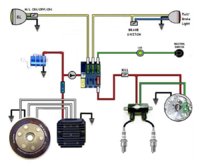
ImageUploadedByTapatalk1460480035.436899.jpg

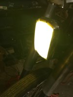
What I've done so far is solder and shrink wrap the wires from my headlight and brake light. They are both aftermarket. The headlight is a one wire so I drilled a small hole in the bulb housing and attached a ground wire with a sheet metal screw and it's working fine so far. I've also figured out how to attach the rear brake light to the factory rear brake switch but we'll touch on that later.

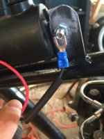
Thus far both lights work as intended when off the bike and attached to a battery. But alas when on the bike I'm having trouble establishing a good ground for the headlight. So the fun begins, my intention was to ground the headlight on the coil mount hidden under my tank, but it's not working. I thought I had enough bare metal exposed on the frame to ground it but I'm doing something wrong. Hopefully daddyg or another more experienced can help sort this out so we can move on to the brake light. Here's a pic of what I'm trying to do for the ground.
ImageUploadedByTapatalk1460480617.674827.jpg

Just to clarify I'm just using cheap solder less connections on this particular endeavor to establish I'm going in the right direction. It will be tidied up once I know it works.
 
Most of my negatives are directly connected to the battery. The only grounds I use are for the engine and the PMA, where I have removed the paint completely off the engine mounts, and it seems to work well so far.
 
Ok, does the bike run with the PMA and cap? Does the PMA have good output? If it won't then trouble shooting lights may be useless until you have it running and charging.
You can test the lights with a battery. Hook up the battery in place of the cap. This might actually be easier, won't have to have bike running all the time your testing.
With a battery hooked up you will have a constant source of power. Also remember that electricity flows in a circuit. Think circle. Both come from the same root word.
Electricity flows from the power source out to whatever you want it to run then return to the power source.
So check all ground connections, the one you show at the coil mount looks ok to me. Clean bare metal. A thin coat of grease will help prevent corrosion. Check at the cap ground.
Leo
 
Thanks for the replys guys. Leo, as of now I am using a regular battery to check things out. I am not starting the bike, I just wanted to make sure everything worked correctly individually before running everything together. So this is literally the beginning stages where I've got everything wired up, but like I said nothing is in a harness so to speak. I've got the headlight ground on the frame as in the pic and the positive from the headlight going straight to the battery. I thought my ground looked fine to but when I hooked it up nothing happened. I thought maybe something came loose so I ran the pos/neg straight to the battery and it lit up. Put the negative back to the the frame and nothing, I'm a little surprised. Maybe I need to take a little more paint and tighten the connection a little better.
 
Is the negative from the battery to the frame a clean connection? Are you sure you're connected to the frame, and not something that ultimately isn't connected to the frame?

I agree, seems like an OK spot for ground to make contact, maybe a little more scrubbing of the paint there, but nothing that I would think would stop the circuit from functioning.
 
As far as I can tell, I'm gonna mess around with tonight after work. I'll report back. You guys are saying to use grease to avoid corrosion, just a general automotive grease ok?
 
What I did was weld a 10-24 bolt to the inside of my electrical box then brought my main ground from the battery up to it and tightened a nut down on it. then anything else that needed grounded I put a ring connector on the wire and added it to the bolt. I have 1 ground running up to the headlight bucket for lights and horn. All other things that needed grounded like start relay rectifier I have in my electronics box and ground them on the same bolt. If you do that make the bolt at least long enough to add all your ground wires on.
 
Hi figure8,
all those little black inverted Christmas trees on your wiring diagram show those components as grounded to the frame in different places.
Betcha everything will work better if all the black wires were to meet at one single 6mm ring terminal and that terminal was grounded to the frame.
And run a big fat ground wire between the frame and the engine too.
 
Appreciate the input guys. I've got the headlight issue sorted out, working fine now, just needed a better ground. Next up will be the brake light/switch.

Not dismissing your ideas, just wanting to get the lights going then we can explore better grounding options.

One down....
ImageUploadedByTapatalk1460526728.745676.jpg
 
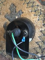
Alright, so now on to the brake light. This is an aftermarket "33 Ford" style light. This is a two wire, one wire for running light and one for brake. In my case the running light is the green and the brake is black. It mentions the option to add a ground which really isn't an option, you need to. So that's what I did, I took out this bolt and ground off some of the paint to add my ground.
ImageUploadedByTapatalk1460564205.816695.jpg
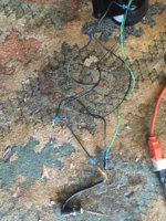
I'm gonna use my rear stock brake switch on my 81 which has brown wire and a yellow wire. I found running the black running wire to the yellow wire from the brake switch and the green brake wire to the brown brake switch wire did the trick. However, you'll need to double down and run an additional wire out from the green to brown to go to the power source. My thinking was to solder these 3 together and shrink wrap them but I'm all ears if someone has a better suggestion. Again, this is a just a rough visual until I can establish location/length of wire needed.
ImageUploadedByTapatalk1460564637.623790.jpg
The brake switch seen at the bottom of my above pic attaches to the frame and the rear brake rod. I'll throw up a pic when I put it on. So basically when you apply your rear brake it pulls that spring to complete the wiring circuit and lights up the brake light.

I realize I'm not doing anything ground breaking here to a lot of people on this site but I'm hoping this will be helpful to some who are new to bikes and feel overwhelmed by the process.
 
You could also just run a dedicated line from the key switch the the green wire, and then the brake switch would just connect to the black... not sure there's any advantage in that....lol. (Just thinking out loud).
 
You could also just run a dedicated line from the key switch the the green wire, and then the brake switch would just connect to the black... not sure there's any advantage in that....lol. (Just thinking out loud).


I'm open to suggestions here, so it's appreciated!
 
I suppose it comes down to when/how you want power to the tail light... I've seen bikes where they wired the headlight AND tail light on a toggle switch...so they didn't come one without actively turning them on. This was so they could have lighting outside of the motor running and/or key on....as well as killing all lighting with the motor on--which seems dumb, but whatever floats their boat. :) Not sure that's all that important, but another option at least.
 
I guess it really comes down to what I end up using for my power source. I'm leaning towards getting an anti-gravity 4 cell but may stick with a cap, not sure yet.
 
How is your battery connected to the frame and engine? Without a good battery connection to the frame and engine it doesn't matter how well your lights are grounded.

Scott
 
I am going to add my 2 cents here because I do this all the time and sell harnesses.
So far you are doing fine but I would stay to the diagram as much as possible. Plus the big one grounding to a chassis is not 100%. I build harnesses that all the grounds are together and end up at the factory 12mm bolt that is the ground on motor. You can screw up hooking up lights-horn-brake switch but if you screw up a ground it could go back to the IGNITION STOCK/PAMCO/BOYER and burn it up fast.
Here just to give you a out....... I run a ground wire from the head light to the tail light and at the back bone I leave enough wire (NOT CUT) for the factory ground. Now I got a ground from the front to the back without touching frame and I can tie my horn ground to that and any other ground. Makes life easy and you know all is grounded. I have had frames that could not pass a ground from the front of the frame to the rear so I don't use the frame as a ground. All grounds go to 12mm bolt and that is also where battery ground goes. I have seen way too many tail lights and headlight go because of frame grounds.:thumbsup:
Got any questions I am here to help
Rich
 
Rich, appreciate the input. I'm trying to keep wires at a minimum which is why I was grounding to frame, but I trust you more than I do myself. If you've got any pics to contribute that would be great. I'll post some follow up questions later tonight, thanks.
 
Hi figure8,
Listen to Daddy, he's wired up more bikes than you've had hot dinners.
And Brassneck, the "lights off" thing is tradition, mostly by us old farts who are nostalgic about the good ol' days when the sparks were made by a magneto and the dynamo and battery were a separate deal, or indeed, an option.
 
I certainly intend to. Like he said I'll take my chances on the lights but certainly will not with my Pamco.
 
Back
Top