Wiring LED blinkers and tail light

alreadyoutofmydepth

XS650 New Member
Messages
3
Reaction score
0
Points
1
Location
London
Hi all, brand new to the forum - picked up a 1997 Dragstar 650 last Friday, full of hope and ambition. One week on and I'm an embittered old mess, muttering at my shoes!
This is my first ever bike, and therefore first custom project and doubtless I have bitten off way more than I can sensibly chew.

I am struggling to find anything conclusive about converting the old lights to LEDs. I have read various things about requiring relays, but I'm totally confused about what to get, and more importantly, how to install them.

When I removed the back seats and fender, I cut the rear end cable which has five wires connected to the battery. Brown, Black, Yellow, Blue, and Green.

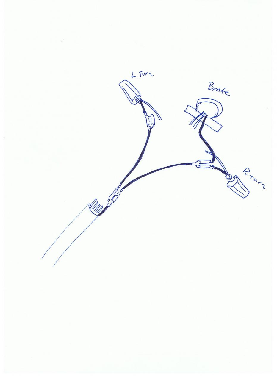
My new LED signals have two cables each, black and red, and my tail light 3 cables, black red and orange. So collectively 6 cables.

I've made a crude PDF with this on, if it helps.

Does anyone have a dummies guide (and I do mean dummy!) of how these cables link up, and what hardware is required? Any help at all really appreciated. Massive thanks in advance.

Richard
 

Attachments

  • LED install .pdf
    85.6 KB · Views: 442
Hi Richard and welcome,
the real London? And a 1997 Dragstar 650?
This is the XS650 forum to which all are welcome regardless of what they ride but the very last XS650 left the factory in 1984.
& howdja get a 650cc "first bike" past the UK's graduated licence laws?
Anyhow, relays use a small current to switch a large current and as LEDs take less current than the bulbs they replace I don't see the need for them in your application.
Mind you, the thing that works the flasher is also called a relay and the flasher system will need one of those.
Here's what the XS650 Yamaha wiring does.
Brown is left signal light. Black is ground. Yellow is stop light. Blue is tail light. Green is right signal light.
You'll have to check your LEDs with a battery to see which wires are what.
My limited understanding of LEDs says they only work one way so you can find out if the red or the black signal wire is the ground. (ground aught to be black but it's best to check)
The stop/tail LED is more complicated.
Whichever wire will work with either of the two others is ground.
Whichever of the other two wires light up brightest is the stop light.
Just connect them, is all. Twist them at first until you are sure they are hooked up correctly, then make permanent connections. Or perhaps better to use bullet connectors?
Note that the stock XS650 signal flasher relay needs the full 57Watts draw of the stock signal & indicator bulbs to flash. Less power than that and the signal lights just come on steady.
Any LED signal set-up needs an LED-compatible flasher to work.
 
You're wiring looks pretty straight forward. And shouldn't be too hard to do. (As stated, the LED signals will need a different flasher to work assuming they weren't LED's before).

So you have 7 wires vs. the 5 that were originally on the wire harness. If you have a wiring diagram...that would help. Without it, you may just need to do some testing (A testing light will work...but multimeter is also your friend here).

You can take all your grounds and connect them to the ground on the harness...my assumption would be all black wires on your new signals and brake light are grounds, and may also be the black from the harness...but definitely double check. (I have seen where black is positive and red is negative on some chinese LED lights).

(Note: There could be a chance that the turn signals are actually ground by the mounting bolt/shaft and the black wire is a running light...so check that as well.)

Your left and right signals are probably powered by the green/brown wires from the harness. Easy to check...simply turn the key on, turn the left signal on...and see which of those wires is powered, then turn it off..if that power goes away that's it...otherwise keep checking....once you figure out left/right...simply connect those to the corresponding signal's red wire (Again, assuming it's the light's positive wire)

Your brake light will have a constant power wire (less-bright illumination) and a switched wire (brighter illumination). You just need to power the orange or red and ground the black to see which is which...and then find out which wire of the harness is powered by the brake switch...again, turn on the bike, pull the brake and see which of the wires (I'd guess blue) has power when you pull the brake. connect your wires and you're good to go.

I would recommend quality crimping/soldering with good connectors.

Hope this helps/makes sense.

Good luck.
 
Guys, thanks so much for the quick responses and supportive advice - especially since (as Fredintoon points out) I'm in the wrong forum! Doh! In the UK, the Yamaha Vstar is called an XVS650 Dragstar, so i guess I've got confused over XVS650 and XS650. Sorry guys.

Seems like your advice is relevant nonetheless, so if it's cool I will stick around and leech your expertise while I can. I'll simultaneously check out the other thread as suggested by TwoManyXS1Bs - thanks for that.

So, next questions;
Brassneck, when you say hook all three black cables to the single black cable from the wiring harness, what precisely should I use to connect them? Is there some sort of 3-into-1 splitter or terminal block, or am I literally just twisting all three cables together, and then twisting onto the harness cable, soldering, then heat wrapping? Sorry for the naivety - just never done this before.

I'll get the multimeter as suggested to figure out the left/right cables.

Fredintoon, yes, it's the flasher relay the LED's seem to need. Does anyone have any how it's attached/installed?

Thanks again everyone - really appreciate the help.

P.S. Fredintoon, in the UK provided you are over 24 yrs and hold a full car licence, you can sit your test on a 600cc/650cc and then ride whatever you like thereafter. The testing is quite extensive though - 7 days mixed classroom and road riding. Although that's already feeling very short compared with the time this f***king build is probably going to take me :wink2:

Hi Richard,
your bike should already have a flasher relay on it somewhere.
It should be plugged into the bike's harness with a 2 or 3-way plug & socket.
XS650 has a 3-pin connector with brown; brown/white & green/white wires.
It's likely the stock flasher which most likely won't work with LEDs so you'll need to find the original unit and replace it with an LED-compatible one.
Next little wrinkle:- if your bike has the same signal self-cancelling feature as the XS650 that'll only work with the stock flasher and replacement flashers ain't wired right so no more self-cancel.
Joining wires:-
Best is aircraft grade crimp connectors.
The cost of the special pliers alone will bring tears to your eyes.
Next best is solder and shrink-sleeve.
The choice of those who won't scream like a girl when molten solder drips onto their skin.
Long way last at 70% conductivity if they are done perfectly is el-cheapo crimp connectors from Halfords.
Back when I took my test at age 18 you could hang L-plates on a Vincent if you could put up with the embarrassment.
I passed my test on a James 197 and bought a 350 Gold Star the next day.
 
So, next questions;
Brassneck, when you say hook all three black cables to the single black cable from the wiring harness, what precisely should I use to connect them? Is there some sort of 3-into-1 splitter or terminal block, or am I literally just twisting all three cables together, and then twisting onto the harness cable, soldering, then heat wrapping? Sorry for the naivety - just never done this before.

No worries...everyone starts somewhere, and asking is way better than guessing. Wiring up lights can seem daunting, but it's pretty much the easiest part of an electrical system, in my opinion...and a good way to get a feel for it so when you move onto more complex wiring, you have some basic knowledge. :)

There are some great threads on here about electrical systems properties, how-to's, and overall how charging systems, lighting, etc. work...I won't repeat that here, but if you're sticking around...probably a good idea to read up on those.

One summary that I think is pretty well written (although not specific to any one bike) is this: http://www.bikeexif.com/motorcycle-wiring

OK...so for connections, this is up to you. (With the assumption that the black wires are all grounds for example), then the first question to ask is "Do I need to disconnect these in the future?" If yes, then you're looking to connect them with some type of connector rather than "hard wiring" them together. They make bullet-type connectors, they make spade-type connectors, and they make multi-prong connectors... it's really up to you and what you like.

I personally like bullet-type connectors that are insulated/weather proof...(if they are going to be exposed). And yes, you can get 2-into-1 female bullet connectors...maybe they make three into one as well? (Not sure). Note: You should get a good crimping tool, solder the connections and heat shrink them as a general process...this will ensure a great, long-term application.

Anyways, you take the black ground from the harness and crimp/solder a female connector (2-into-1) and you can take two black wires, crimp/solder on a male bullet connector to each one (with enough wire to run up to the turn signal location). Then crimp another female 2-into-1 connector at their ends.

So now you have your wiring harness's black wire, with 2 black wires connected to it and both go to each side of your turn signals. Then you add male bullet connectors to the black wires from your turn signals...and one to the brake light. And simply connect them. Note, one side will only have one wire connected...the other side will have two connected.

Here's a simple drawing (I'm not an artist)...but this is just to illustrate the idea:
full


This is just one way to do it. Hope it helps.

Good luck.
 
This is all incredible helpful. Thanks so much everyone. Genuinely very humbled at the kindness and consideration. Hugely appreciated.

Last night I dismantled the rear end (fender/rear lights/signals etc) which I'd pulled off on day one and threw in a corner of my garage. I found that the old blinkers just plug into a sub harness with the bullet connectors. My new LED's were already provided with bullet connectors which just slide into these!! Seems too good to be true, but let's see!

Once those are set, all I should need to do is rig up the tail light, and reconnect the main rear harness to the sub-harness where I'd cut it.

I'll have a try at this tonight and see how far I get. I made some Wenge signal mounts with brass bolts for the rear end (see pic), so that with the LED's it's a deliberate mixture of old and modern - dying to see them actually running.
 
Hi Richard,
um, what pic? Nothing showing on my screen.
From what you post and if it's done correctly everything will light up as it should except the flashers will come on steady if the stock flasher relay won't work with the LEDs' reduced current draw.
 
Back
Top