wolds
XS650 Enthusiast
So I have been busy working on the conversion of my clutch system from mechanical to hydraulic and made great progress over the weekend. The mod as others have pointed out is pretty straight forward. I used the following components.
Clutch M/C: 1984 Honda Interceptor VF750 (14mm bore) (ebay)
Clutch Slave: 1986 Kawasaki GPX750R (34mm bore) (local MC junk yard)
Clutch push-rod: 8mm Shaft 300mm 12" Hardened Rod Rail Linear Motion 3D Printer XYZ for lm8uu (ebay)
backing plate: 1/4" aluminum
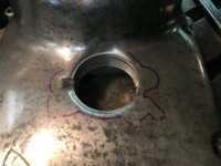
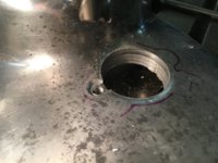
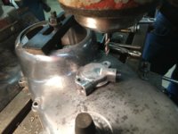
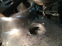
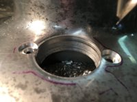
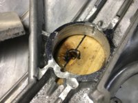
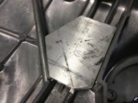
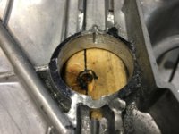
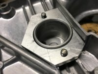
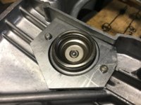
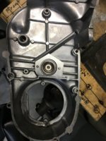
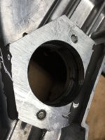
I started by making a plug out of delrin that would fit into the existing opening of the clutch mechanism so that the pilot of the 1-3/8" hole-saw would remain centered in the existing opening assuring alignment with the clutch rod. I used a vertical mill to make the hole and the two counter bores for the mounting screws but a drill press would also work. Next I trimmed the webs on the backside enough that the aluminum plate would lay flush. Once JB welded in place I drilled pilot holes through the aluminum and tapped to 6X1mm. For my install I used three stainless washers stacked under the mounting ears to get the slave to rest on the ears so that when screwed down the slave would remain true and not become distorted from being bent around the radius of the cover. The clutch push-rod ended up being 272mm long in my case. I dished the end that contacts the slave so that the rod would remain centered on the ball bearing that it rides on that is set in the piston the other end retains the ball bearing that was used in the original two-piece rod. I'm going to fabricate a felt pad that will seal the end of the piston and will contain the small dab of grease to provide lubrication between the rod and the ball bearing. Because I have the engine on my bench with the RH side cover off I was able to measure the linear travel of the stock setup against the hydraulic unit with a dial indicator. I measured .056" of travel for the stock setup and .090" for the new one. This setup should make finding neutral when the motor is at operating temperature much easier. When the bike is back on the road I'll report my results. I have included a few pictures for clarity.
Clutch M/C: 1984 Honda Interceptor VF750 (14mm bore) (ebay)
Clutch Slave: 1986 Kawasaki GPX750R (34mm bore) (local MC junk yard)
Clutch push-rod: 8mm Shaft 300mm 12" Hardened Rod Rail Linear Motion 3D Printer XYZ for lm8uu (ebay)
backing plate: 1/4" aluminum
I started by making a plug out of delrin that would fit into the existing opening of the clutch mechanism so that the pilot of the 1-3/8" hole-saw would remain centered in the existing opening assuring alignment with the clutch rod. I used a vertical mill to make the hole and the two counter bores for the mounting screws but a drill press would also work. Next I trimmed the webs on the backside enough that the aluminum plate would lay flush. Once JB welded in place I drilled pilot holes through the aluminum and tapped to 6X1mm. For my install I used three stainless washers stacked under the mounting ears to get the slave to rest on the ears so that when screwed down the slave would remain true and not become distorted from being bent around the radius of the cover. The clutch push-rod ended up being 272mm long in my case. I dished the end that contacts the slave so that the rod would remain centered on the ball bearing that it rides on that is set in the piston the other end retains the ball bearing that was used in the original two-piece rod. I'm going to fabricate a felt pad that will seal the end of the piston and will contain the small dab of grease to provide lubrication between the rod and the ball bearing. Because I have the engine on my bench with the RH side cover off I was able to measure the linear travel of the stock setup against the hydraulic unit with a dial indicator. I measured .056" of travel for the stock setup and .090" for the new one. This setup should make finding neutral when the motor is at operating temperature much easier. When the bike is back on the road I'll report my results. I have included a few pictures for clarity.
Attachments
-
 IMG_2175.JPG145.2 KB · Views: 321
 -
 IMG_2176.JPG166.4 KB · Views: 294
 -
 IMG_2177.JPG165.7 KB · Views: 309
 -
 IMG_2178.JPG149.1 KB · Views: 273
 -
 IMG_2179.JPG147.7 KB · Views: 314
 -
 IMG_2181.JPG203.9 KB · Views: 302
 -
 IMG_2182.JPG189.1 KB · Views: 277
 -
 IMG_2183.JPG179 KB · Views: 263
 -
 IMG_2184.JPG159.1 KB · Views: 262
 -
 IMG_2185.JPG194 KB · Views: 302
 -
 IMG_2186.JPG173.4 KB · Views: 289
 -
 IMG_2187.JPG180.1 KB · Views: 322
 -
 IMG_2188.JPG185.6 KB · Views: 304
 -
 IMG_2190.JPG171.9 KB · Views: 273


