XS650 Clutch Pushrod experiment & tidbits

I'm curious about something. On my bike, the first clutch pull in the morning has a little catch in it. Builds up tension and then lets go. It's always just the very first pull and it's always there, and it's always been that way. Something is settling in overnight, just for that first clutch pull.

It's been there through many changes, so I wonder if it's universal? It's been there through a new cable, through a new lever, through filing on the lever to smooth it on the cable, through a worm gear disassembly and regreasing, through a bushing change and a seal change, through many cover removals,

I don't consider it a problem but I wonder if anybody knows what I'm talking about...

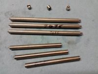
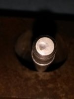
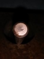
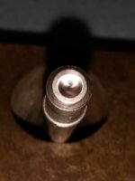
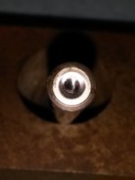
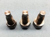
Yeah, ran into something like that early on in these experiments. It went away after I reground the adjuster screw and pushrod ends. Figured that it may have been one or more of the balls settling to the bottom of the bore (either mainshaft or worm drive), then 'popping' into place in a dimple when the clutch was pulled. And, would remain in the dimple(s) after that, possibly due to grease sticktion or slack take-up. Since then, I've made sure to dimple the shaft at least a few thou so the ball(s) wouldn't fall all the way down in the bore.

Thanx for noticing this, I'll watch for this more closely as the experiments progress...
 
Hi, xs650dreamer! I've been running on the 304 stainless pushrod, riding/evaluating when it's warm.

The expansion differential with this pushrod is indeed a little less than the standard 1-piece steel pushrod. It takes about 1 turn of the handlebar adjuster after the engine is hot.

I'd like to get my hands on a bad/damaged aluminum part of a 2-piece pushrod, to split the ends, to measure the factory's end-cap inner dimensions. I'm planning to use 7/32" for the interference fit diameter, which is about half the cross-section area of a 5/16" rod, but would like to know what diameter and depth Yamaha used.

Otherwise, hunkering down during the cold blasts...
 
Thanx, dreamer. I have dogbunny's 2-piece setup, excellent condition, will be using it for comparisons. I cringe thinking about destroying a perfectly good rod. Would rather have a bad one to examine (collectable parts guilt). I have a regular steel rod, and another experimental 304 rod, that I could swap with someone so they wouldn't be stranded...
 
Well, finally warmed up enuff to get things done. Hummingbirds showing up, must be a sign.

Machined the pieces to make 3 of the experimental bi-metal rods:
 

Attachments

  • 20140318_193154.jpg
    20140318_193154.jpg
    114.4 KB · Views: 359
Dogbunny gave me a 2-piece clutch pushrod for this experiment. The outer steel rod shows a feature that should be of interest to others. Close examination shows ball-bearing wear dimples that are off center, equal and opposite on both ends. This rod would have wobbled in the pushrod bushing, perhaps producing more drag and less travel.
 

Attachments

  • 2Piece01.jpg
    2Piece01.jpg
    21.6 KB · Views: 298
  • 2Piece02.jpg
    2Piece02.jpg
    19.7 KB · Views: 309
To allow the clutch worm actuator adjuster ball to seek its own center, preventing side loads on the pushrod, the adjuster tips need to be resurfaced, squared-off. The adjuster on the right has experienced about 200 miles worth of frequent clutch actuation. The slight wear dimple appears to be centered. It will be resurfaced before returning to service.
 

Attachments

  • ClutchAdjusterTips.jpg
    ClutchAdjusterTips.jpg
    133.9 KB · Views: 350
Welcome to the island of Dr. Moreau. Here's a collection of clutch pushrods under test.
One of the BiMetal rods is installed, adjusted, ready to test.
But NOT while it's 44°F outside...
 

Attachments

  • XSperimentalRods.jpg
    XSperimentalRods.jpg
    146.5 KB · Views: 358
Welcome to the island of Dr. Moreau. Here's a collection of clutch pushrods under test.
One of the BiMetal rods is installed, adjusted, ready to test.
But NOT while it's 44°F outside...

If I was a betting man, I would put my money on the 1 piece all aluminum rod, as being the most suitable. If you test the aluminum rod, will it have steel tips to prevent excessive wear?

Very interesting testing of the various rods.....................I'm looking forward to the results.
 
If I was a betting man, I would put my money on the 1 piece all aluminum rod, as being the most suitable. If you test the aluminum rod, will it have steel tips to prevent excessive wear?

Very interesting testing of the various rods.....................I'm looking forward to the results.

Hey, RG! That 7075 aluminum rod is all aluminum, no steel tips. The ends are dimpled, want to see if this tough stuff holds up to the ball-bearing pressures without the steel tips. Also want to see how it handles passing thru the seal and bushing.

I did an impromptu pressure/buckling test on a 10" piece, and it started showing signs of buckling at about 1,000 lbs. The expected 400 lbs for clutch disengagement is safely well below that.

The other 2 bi-metal rods went to DogBunny (Austin) and XS650dreamer (Arizona). So, they'll be testing as well in the warmer weather. Want to see if these rods at least equal the expansion feature of the stock 2-piece rod, and DogBunny + XS650dreamer are already running the 2-piece rods, good for comparison.

These three bi-metal rods were made to similar dimensions as the 2-piece, 6" aluminum, 3.7" stainless. This puts the joint a little more than an inch behind the bushing. I'd rather have the joint closer to the bushing, for support and away from any buckling zone.

So, thinking about a next-gen version of 7" aluminum and 2.7" stainless. These first ones are basically proof-of-concept.

Maybe you'd like to try one of these?
 
Last edited:
So, I am assuming the "coupling" of the two-piece rods you made is an interference fit, with the aluminum piece being the "male." After assembling, did you test for straightness at the joint?
Looking forward to getting my test unit, Thank You!
 
So, I am assuming the "coupling" of the two-piece rods you made is an interference fit, with the aluminum piece being the "male." After assembling, did you test for straightness at the joint?
Looking forward to getting my test unit, Thank You!

That's right! The main joint is a 5mm long stub of 5mm diameter on the end of the aluminum, interference/press fit into 5mm socket in the stainless. Interference fit of 0.0005", and locked-in with permatex 64000 shaft retainer (would have preferred loctite 648, but couldn't find it here).

Straightness, thanx for reminding me. The rod stock I received was less than stellar quality. Slight staining (from setting so long in poor storage), and slightly bent. I spent literally hours straightening rods, getting them less than 0.002" runout.

The assembly jig keeps the rods aligned during assembly, but they were checked again after bond cure to be sure they were within that 0.002" runout.

So, here's where you come in. I'm hoping that the USPS gorilla is on vacation during your delivery, but you never know. When the rod arrives, roll it on a flat surface to see if it remained straight. It won't be perfect, you'll likely see slivers of light between the rod and surface, but if the light slivers are more than 0.003", the gorilla was involved.

If need be, you can try straightening it yourself, but this is some tough stuff, doesn't bend like regular aluminum. Since I have the tools to check/adjust runout, you could just send it back to me, I'll straighten it, and gorilla-proof repackage it back to you...
 
Back
Top