2M or dps650rider....................do either of you have an aluminum push rod that is for sale?
-
Enjoy XS650.com? Consider making a donation to help support the site.
XS650.com receives a small share of sales from some links on this page, but direct donations have a much greater impact on keeping this site going.
You are using an out of date browser. It may not display this or other websites correctly.
You should upgrade or use an alternative browser.
You should upgrade or use an alternative browser.
XS650 Clutch Worm Actuator experiment & tidbits
- Thread starter TwoManyXS1Bs
- Start date
RG, I can make you one from 7075T6. PM me if you want to join the game...
2M ....................PM sent
dps650rider
XS650 Addict
Y'know, I thought maybe the wide-tire / offset-sprocket folks would catch on this mod.
You're the first I've heard to do this for that reason.
My clutch is a bit stiff because I put in heavier springs. Anything I can do to reduce the effort without compromising full disengagement is welcome. So what I did probably helped and I'm pretty sure I can go more since I just went enough to clear the sprocket.
So, I dug out my collection of worm gears and it turns out, I had more than I thought. Besides three 650 variants, I have both an XS500 and XS400 "1L9" worm. You were right 2Many, besides the step-down off-set, the 400 and 500 worms are clocked a little differently .....

The 650 arms fully retracted all clock about at the 7 o'clock position, as you've noted .....

The 400 and 500 arms are more like 7:30 or 8 .....

The arm length between these two differs as well. The XS500 arm is rather short, maybe shorter than ideal for us. It actually matches the length of the early XS1 650 arm .....

The XS400 arm is longer and matches the mid-mount location on the later 650 worm. This one may be ideal for us. Also of note is that the 400 arm appears to be stamped with it's part number 3 digit prefix (1L9). This should make I.D.ing them easy .....

So, the clocking may need adjusting a spline or two but I guess installing one is the only way to know for sure. If we get very lucky, maybe these will match your re-clocked 650 version the way they are. Wouldn't that be nice, a drop-in re-bent, re-clocked worm.
I've also given some thought to the short 500 arm. Just flattening it out would make it a little longer and maybe long enough. It would be sort of a compromise between the stepped up originals and the stepped down versions, but could offer some improvement. The only slight change in stepping may also eliminate the need to cut the cable seat on the case.
I was also thinking, your original premise here was that the high mounted cable was inducing a "tip over" effect in the worm and binding it. Couldn't dropping the cable attachment too low have the same effect, just in the opposite direction? The high mount would lift up on the worm (besides twisting it) and cock it away from the arm. A mount that was too low might pull down on the arm as it twists, cocking the worm towards the arm. Maybe an arm that sticks straight out is the best compromise?
The 650 arms fully retracted all clock about at the 7 o'clock position, as you've noted .....
The 400 and 500 arms are more like 7:30 or 8 .....
The arm length between these two differs as well. The XS500 arm is rather short, maybe shorter than ideal for us. It actually matches the length of the early XS1 650 arm .....
The XS400 arm is longer and matches the mid-mount location on the later 650 worm. This one may be ideal for us. Also of note is that the 400 arm appears to be stamped with it's part number 3 digit prefix (1L9). This should make I.D.ing them easy .....
So, the clocking may need adjusting a spline or two but I guess installing one is the only way to know for sure. If we get very lucky, maybe these will match your re-clocked 650 version the way they are. Wouldn't that be nice, a drop-in re-bent, re-clocked worm.
I've also given some thought to the short 500 arm. Just flattening it out would make it a little longer and maybe long enough. It would be sort of a compromise between the stepped up originals and the stepped down versions, but could offer some improvement. The only slight change in stepping may also eliminate the need to cut the cable seat on the case.
I was also thinking, your original premise here was that the high mounted cable was inducing a "tip over" effect in the worm and binding it. Couldn't dropping the cable attachment too low have the same effect, just in the opposite direction? The high mount would lift up on the worm (besides twisting it) and cock it away from the arm. A mount that was too low might pull down on the arm as it twists, cocking the worm towards the arm. Maybe an arm that sticks straight out is the best compromise?
Last edited:
So, I dug out my collection of worm gears and it turns out, I had more than I thought. Besides three 650 variants, I have both an XS500 and XS400 "1L9" worm.
Haha, box full of clutches, too. I had a feeling the disease runs deep here.
I went ahead and ordered a couple of those 'half price' worms off eBay.
I want a closer look as well.
You were right 2Many, besides the step-down off-set, the 400 and 500 worms are clocked a little differently .....
The 650 arms fully retracted all clock about at the 7 o'clock position, as you've noted .....
The 400 and 500 arms are more like 7:30 or 8 .....
Interesting. The ones with the incorrect 'clocking' could still be salvaged for the worm screw, like for this mod, or for the 'foot clutch' guys.
Edit: I've found some excess 'flashing' of nylon and protruding burrs on the top of a couple of nylon worm bodies. Trimming those down improved this 'clocking'.
The arm length between these two differs as well. The XS500 arm is rather short, maybe shorter than ideal for us. It actually matches the length of the early XS1 650 arm .....
That IS short. My original XS1B's arm was short like that.
It worked, but was a (*grunt*) bear to pull.
I suppose the XS400 and XS500 clutches have weaker springs, so this may not have been an issue.
The XS400 arm is longer and matches the mid-mount location on the later 650 worm. This one may be ideal for us. Also of note is that the 400 arm appears to be stamped with it's part number 3 digit prefix (1L9). This should make I.D.ing them easy .....
It sure looks like a viable 'drop-in' substitute.
So, the clocking may need adjusting a spline or two but I guess installing one is the only way to know for sure. If we get very lucky, maybe these will match your re-clocked 650 version the way they are. Wouldn't that be nice, a drop-in re-bent, re-clocked worm.
Absolutely! And, at half the price (for now).
Using one of your pics from 3 years ago, you show the ideal starting angle of the worm's lever.
Since the clutch cable will pull the arm's clevis only about 0.375" - 0.450", a typical sweep of around 16° - 18°, it shouldn't be too hard to keep the lever in the more advantageous 80°-90° zone.
I've also given some thought to the short 500 arm. Just flattening it out would make it a little longer and maybe long enough. It would be sort of a compromise between the stepped up originals and the stepped down versions, but could offer some improvement. The only slight change in stepping may also eliminate the need to cut the cable seat on the case.
I've seen some other actuators that are just like that, the lever arm protrudes straight out, flat.
Even that would be an improvement.
And, just a little extra length on a short arm is a relativly large improvement.
I was also thinking, your original premise here was that the high mounted cable was inducing a "tip over" effect in the worm and binding it. Couldn't dropping the cable attachment too low have the same effect, just in the opposite direction? The high mount would lift up on the worm (besides twisting it) and cock it away from the arm. A mount that was too low might pull down on the arm as it twists, cocking the worm towards the arm. Maybe an arm that sticks straight out is the best compromise?
The 'ideal' clevis hole height would be at the wormscrew body's midpoint (visualize a handheld paint roller). The reinforcing rib in the left side cover interferes with the clevis if the arm is bent down too far. In fact, you can't even get low enuff to meet that midpoint. I found that about 0.200" drop is max. So, I believe we're safe there.
The supply of XS650 clutch worms has been drying up, and getting expensive.
I think you've found an untapped source of plentiful and half-price worm parts here.
Until the vendors catch on...
Last edited:
Yes, that happened with the TX750 swingarms. Should have kept my mouth shut until I at least scored a couple cheap ones, lol. My pic you posted is just showing the correct position of the cable arm if it is started into the female part correctly. It's fully inserted so probably won't be exactly there once the cable is attached. If you started mating the 4 splines incorrectly, the arm would end up 90° or 180° from where it's pictured.
Last edited:
I just received and examined a couple NOS clutch worms, and thought I'd post a summary description of what's been found.
Note: All these worms are supposed to use the same nylon worm body, with the same 8mm adjuster and ball.
All these worms have the same middle 16340 part number, but the suffix may vary.
The numbers identified below are the 3-digit model-code prefixes.
The XS650 worms, with the goofy upward/outward lever bend:
256 worm, mid-70 to at least 71, maybe 72-73:
1.2" (30mm) center to clevis hole distance.
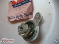
447 worm (thanx, 5twins):
Unknown center to clevis hole distance.

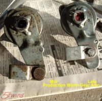
Mid to late '70s to 80's worms (thanx, 5twins)
Unknown part numbers.
1.4" (35mm) center to clevis hole distance, for the unit on the right.
Unknown center to clevis hole distance, for the unit on the left.
1T3 (80's XS650) worm:
Unknown center to clevis hole distance.
(We suspect that this may actually be a mis-identified 371 clutch worm)
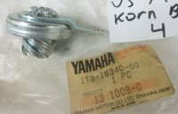
Now, the RD350 (and other 2-stroke etc.), XS360, XS400, and XS500 clutch worms (lever arms bent down):
Note: The arm indexing may not be ideal for the XS650, as noted by 5twins above.
278 (RD350) worm (almost identical to the 371):
1.2" (30mm) center to clevis hole distance.
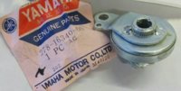
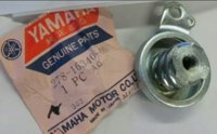
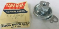
371 worm (XS500) (almost identical to the 278):
1.2" (30mm) center to clevis hole distance.
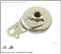
1L9 (XS360, XS400, up to '81) worm:
1.4" (35mm) center to clevis hole distance.
This one looks very viable.
There's only one left in the UK.
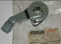
12R (82-83 XS400) worm:
Unknown center to clevis hole distance.
This one looks very promising, but good luck finding one.
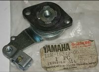
If anybody can post-up the 'unknown' center-to-clevishole measurements, I'll amend this post...
Note: All these worms are supposed to use the same nylon worm body, with the same 8mm adjuster and ball.
All these worms have the same middle 16340 part number, but the suffix may vary.
The numbers identified below are the 3-digit model-code prefixes.
The XS650 worms, with the goofy upward/outward lever bend:
256 worm, mid-70 to at least 71, maybe 72-73:
1.2" (30mm) center to clevis hole distance.

447 worm (thanx, 5twins):
Unknown center to clevis hole distance.

Mid to late '70s to 80's worms (thanx, 5twins)
Unknown part numbers.
1.4" (35mm) center to clevis hole distance, for the unit on the right.
Unknown center to clevis hole distance, for the unit on the left.

1T3 (80's XS650) worm:
Unknown center to clevis hole distance.
(We suspect that this may actually be a mis-identified 371 clutch worm)

Now, the RD350 (and other 2-stroke etc.), XS360, XS400, and XS500 clutch worms (lever arms bent down):
Note: The arm indexing may not be ideal for the XS650, as noted by 5twins above.
278 (RD350) worm (almost identical to the 371):
1.2" (30mm) center to clevis hole distance.


371 worm (XS500) (almost identical to the 278):
1.2" (30mm) center to clevis hole distance.

1L9 (XS360, XS400, up to '81) worm:
1.4" (35mm) center to clevis hole distance.
This one looks very viable.
There's only one left in the UK.

12R (82-83 XS400) worm:
Unknown center to clevis hole distance.
This one looks very promising, but good luck finding one.


If anybody can post-up the 'unknown' center-to-clevishole measurements, I'll amend this post...
Last edited:
OK, some corrections, measurements, and observations - The "371" arm is from the XS500. The "1L9" arm is from the XS400 (and XS360) up to about '81. Apparently the "12R" long arm version was used on the last couple 400 model years ('81 & '82).
The center to clevis hole distance on the "1L9" and the late mid-hole 650 arm is the same, about 1.4" (35mm). I pulled out a spare side cover and mounted the "1L9" assembly. I think it will need some re-clocking. Fully inserted, it's not quite 3.875" (3 7/8") from the cable entrance point. The cable angle to the arm is also right at about 90°. Any and all pulling on the cable will move it past this ideal leverage point, not through it as we seek. Earlier in this thread, you noted 4.1" as the distance with an unadjusted, fully slackened cable connected. You figured about 4.3" fully retracted and with no cable attached to be about an ideal starting point. At near 3.9", the cable will be loose when connected and probably require more adjusting up at the hand lever, maybe more than is available.
So, a re-clocking of the "1L9" worm to achieve something like a 4.2" to 4.4" cable distance when it's fully retracted is probably what we're after.
Last edited:
OK, some corrections, measurements, and observations - The "371" arm is from the XS500. The "1L9" arm is from the XS400 (and XS360) up to about '81. Apparently the "12R" long arm version was used on the last couple 400 model years ('81 & '82).
The center to clevis hole distance on the "1L9" and the late mid-hole 650 arm is the same, about 1.4" (35mm).
Great! Thanx 5twins. Above post corrected with your data.
I pulled out a spare side cover and mounted the "1L9" assembly. I think it will need some re-clocking. Fully inserted, it's not quite 3.875" (3 7/8") from the cable entrance point. The cable angle to the arm is also right at about 90°. Any and all pulling on the cable will move it past this ideal leverage point, not through it as we seek. Earlier in this thread, you noted 4.1" as the distance with an unadjusted, fully slackened cable connected. You figured about 4.3" fully retracted and with no cable attached to be about an ideal starting point. At near 3.9", the cable will be loose when connected and probably require more adjusting up at the hand lever, maybe more than is available.
So, a re-clocking of the "1L9" worm to achieve something like a 4.2" to 4.4" cable distance when it's fully retracted is probably what we're after.
Good info! Calculating a 'reclocking' of that "1L9" worm, from 3.9" to 4.2" (0.3" min), over a 1.4" clevis hole sweep, would require a 12°-13° counterclockwise adjustment. That translates to about a 0.042"-0.046" lateral travel. It may be possible to grind/shave that amount from the top of the nylon worm body to achieve that "reclocking".
The excess metal shroud atop the nylon worm body on the left can be ground down quite a bit. Since the nylon is locked into the metal shroud by the extrusion holes, clamped down by the two mount screws, and only sees compression from the metal worm screw, I see no issues with shaving a little off the top. Picture from this post:
http://www.xs650.com/forum/showpost.php?p=321662&postcount=49
View attachment 37465
Grinding some off the top of the nylon worm, I like that idea. It should certainly be easier than grinding, pressing apart, re-clocking, then re-welding the arm. You could probably just tape a piece of 320 wet/dry paper to a flat surface and work the top of the worm against it. That .042"-.046" is only about 1mm so it shouldn't take too much work or time to remove. I'm sure you could get it just where you wanted it too without too much trouble. Sand a little, re-assemble and measure, sand some more, re-check, etc., until you had it just right.
Once the weather breaks around here in a few weeks, I'm going to have to pull my left cover and check just how my current arm sits with a properly adjusted cable attached. That should give me a better idea of exactly how much to re-clock a "1L9".
Once the weather breaks around here in a few weeks, I'm going to have to pull my left cover and check just how my current arm sits with a properly adjusted cable attached. That should give me a better idea of exactly how much to re-clock a "1L9".
You certainly have a good grasp of this subject. It's nice to be on the same page.
The top grinding is something I'd probably do offhand on my disc sander, with 100 grit. Could also try with a drill and sanding disc, clamped in a vice, trigger locked 'on'. Yep, just about 1mm off the top.
There's precious little clearance between the edge of the seal cup and the heads of the 2 mount screws. A couple little 'dings' on the sealcup edge, where the worm is fully seated, or a little bit ground off the screw heads, or low-height button screws, should give plenty of clearance.
This has been a great thread. I have no experience riding my xs so I can not speak from experience. I have a friend that has a xs bobber and his clutch is a killer to pull, I told him about this thread here on xs650 2 riding seasons ago. But as I build mine all the wile I was not looking forward to a arm match while riding. I hope to gain the know how to fix mine or build it with a easy clutch pull.
Are the tools floating around to do these mods? are they listed somewhere? Keep up the great research and work.
Are the tools floating around to do these mods? are they listed somewhere? Keep up the great research and work.
Hey, cruzin, thanx for the kudos!
At 194 posts, so far, you get a gold star for endurance.
Or a purple heart.
Yes, tools are important. And more tools. Plus a bit of blacksmithing metal whackery skills.
I love to tinker, and there's things that I want that don't exist. That's one of the reasons I love this forum, many gifted/talented craftsmen on here.
This clutch worm mod actually has 2 simple premises:
- To educate folks, in excruciating detail, about the workings of the clutch mechanism.
- Hopefully, MikesXS would do a simple "Request-for-Change" to their current clutch worm offering, by having the worm's lever arm bent down, similar to the XS400/XS500 design.
If you study the current bend profile of the lever arm, it would appear that someone stuck the lever in the press die backwards, and that 'mistake' continues to this day.
Such a simple thing, huh?
Yes, I noticed that clearance issue with the screw heads. There's slightly over a MM available so the worm could be reduced in height by 1mm. The Phillips screw heads are 3mm tall. I checked on low head Allens but unfortunately, they are 3.5mm tall so are no help .....

I checked my different female worms. All measure pretty near the same height, around 22mm .....

Most of mine are like the ones you've encountered. The nylon insert is flush with the metal outer case or that case is a little higher. The one that differs is pictured above. The nylon actually sits above the metal. This is the one I'll probably sand down. I have another that appears to have been filed or sanded by the factory. I guess maybe the metal was sticking up too much and probably made the unit too tall. The way it's been ground down, it's at 22mm tall now .....

I checked my different female worms. All measure pretty near the same height, around 22mm .....
Most of mine are like the ones you've encountered. The nylon insert is flush with the metal outer case or that case is a little higher. The one that differs is pictured above. The nylon actually sits above the metal. This is the one I'll probably sand down. I have another that appears to have been filed or sanded by the factory. I guess maybe the metal was sticking up too much and probably made the unit too tall. The way it's been ground down, it's at 22mm tall now .....
Last edited:
That 'ultimate' was just a name I gave to the welded-up version. In here:
http://www.xs650.com/forum/showthread.php?p=326479&highlight=ultimate#post326479
Glennpm also welded-up a version like this.
I guess you could call it 'ultimate' because the welding reinforced the lever arm, minimizing any flexing, the arm has a 7°-8° angle to point the clevis to the cable hole in the cover, and the return spring perch is high, so the return spring isn't fighting the worm's descent into the nylon body. Plus, it's given me the best evaluation scores. It's the worm that I've been running now...
Well, the weather finally broke around here and I've had a chance to get under that left cover. My intent was to try to get a functioning "1L9" worm install without having to cut/grind/weld the arm to achieve the re-clocking necessary. 2M suggested sanding down the nylon worm a little which is what I did. It worked out pretty good.
Besides swapping worms, I also addressed a couple other things. 2M noted a rather pronounced ridge around the hole in the cover that the worm inserts into. I found this on my cover too. This explains why the worm binds if you tighten the mounting screws much past snug. The screws pull the "ears" down and that distorts the worm portion .....

A couple minutes with medium and fine 1" Roloc discs in a die grinder made short work of removing the ridge. The nylon part of the worm can now be screwed down good and not distort at all .....


Before pulling it, I checked my stock worm. With the cable and worm adjusted, the arm was at just slightly less than 90° to the cable. Distance from the cable entrance at the top of the case to the center of the cable connector pin was right at about 4". Cable removed and worm fully retracted showed 4 3/8". The "1L9" was at 3 7/8" fully retracted and no cable attached, hence the need for some re-clocking .....

A couple minutes of sanding against some 150 paper laid on a sheet of glass knocked 1 to 1.5mm off the worm .....

It now measures just under 21mm .....

That lets the male portion screw in more, right down to where the tin seal holder is resting on the mounting screws. This is about all you'll get .....

But, it's enough to re-clock the worm. You now get the more favorable less than 90° cable to arm angle and the cable distance grows to 4 1/8" .....


Besides swapping worms, I also addressed a couple other things. 2M noted a rather pronounced ridge around the hole in the cover that the worm inserts into. I found this on my cover too. This explains why the worm binds if you tighten the mounting screws much past snug. The screws pull the "ears" down and that distorts the worm portion .....
A couple minutes with medium and fine 1" Roloc discs in a die grinder made short work of removing the ridge. The nylon part of the worm can now be screwed down good and not distort at all .....
Before pulling it, I checked my stock worm. With the cable and worm adjusted, the arm was at just slightly less than 90° to the cable. Distance from the cable entrance at the top of the case to the center of the cable connector pin was right at about 4". Cable removed and worm fully retracted showed 4 3/8". The "1L9" was at 3 7/8" fully retracted and no cable attached, hence the need for some re-clocking .....
A couple minutes of sanding against some 150 paper laid on a sheet of glass knocked 1 to 1.5mm off the worm .....
It now measures just under 21mm .....
That lets the male portion screw in more, right down to where the tin seal holder is resting on the mounting screws. This is about all you'll get .....
But, it's enough to re-clock the worm. You now get the more favorable less than 90° cable to arm angle and the cable distance grows to 4 1/8" .....
Last edited:
Similar threads
- Replies
- 20
- Views
- 4K
- Replies
- 12
- Views
- 3K
- Replies
- 52
- Views
- 21K
- Replies
- 182
- Views
- 41K
