XS650 Clutch Worm Actuator experiment & tidbits

+1 on this being a poor design all around. I THOUGHT there was an early 3 ramp but have not been able to find one now don't know where that idea came from....

Honda CB350 used two plates with ball bearings and ramps Seems like a more robust, lower friction design. But the Honda twins forums have guys pulling their hair out getting the CB clutches adjusted right also. One downside is if the cable is too tight it pulls the balls beyond the ramps, and there you sit with no clutch!

Triumph used an almost identical mechanism with 6x ramps . Not sure of date but presumably contempoary with the xs650. Did Triumph licence the design to Yamaha ?

Much better construction and design with shallower ramps giving a smoother operation but presumably less lateral travel
 

Attachments

  • worm t100.JPG
    worm t100.JPG
    14.7 KB · Views: 382
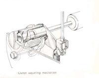
...It might be interesting to look to see how other bike manufactures have solved this problem of mechanically operating the clutch...

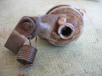
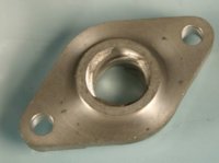
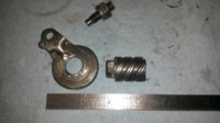
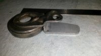
Here's a pic of the non-plastic pot-metal style used on many early Hondas. Adjustment from the outside. Simply loosen the clamp, use a coin to adjust the housing, tighten.

... I threw up a youtube video of my clutch worm mechanism installation back in September . I found that I couldn't even tighten my worm gear fixing screws at all without the arm becoming too stiff to operate. I thought at first it was a hydraulic effect of too much grease but from what 5twins has said it looks like the fixings are distorting the body somehow.

I'll need to find a cure pdq as the bike is nearly ready to use and the worm drive is still only finger tight.
Excuse the hyjack twomany but I thought this problem was sort of relevant and could effect other owners

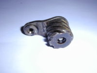
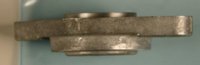
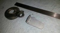
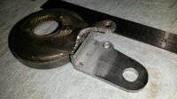
Not a hijack, quite relevant! In your pic, your worm drive is in much better shape than the junker I'm experimenting with.

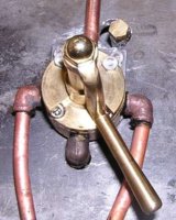
Might I suggest that you first find which of the two orientations gives the best feel, then mark the mount ears 'top' and 'bot' for later reference.

Then, you could bend the arm down a little further out than I did mine, away from the delicate seal cover. Let the bent arm droop down, say at a 45° angle. It doesn't need to be horizontal. Just get it as low as possible without rubbing on the cover's reinforcing rib. You'll probably need to use the outer hole (if you have one) so that the lever hole to rotational axis is about 1.4"-1.5".

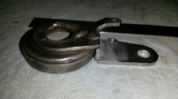
Lastly, pack it well with grease! I use a lighter viscosity teflon grease (in previous pic). Don't run it dry.
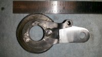
And you can snug the screws down a little, the binding and 'hydraulic' feel will be insignificant when exposed to 100+ lb cable tension and 300-400 lb pushrod force...
 

Attachments

  • clutch450.jpg
    clutch450.jpg
    20.3 KB · Views: 496
thanks twomany thats great advice about reversing the mount 180 . I was also going to try shimming the mounting ears a little to see if I could reduce the distortion on the worm housing case.

I've adjusted my clutch and it feels really smooth with a light pull even with the clevis on the inner pin hole. Its easily moved to the outer hole and readjusted though if I find the clutch operation too sharp. The only problem is the whole mechanism is likely to 'self-eject' after about 3 miles lol:D

I've been looking through ebay at all the other bikes using worm drives and there are surprisingly few
A couple of Suzuki RL-250 etc a Honda Electra a 79 Kawasaki and an XS400 which appears almost identical.
There is a XS1B worm mech on ebay and although early it still has the nasty cheap pressed steel arm tacked onto the worm drive.
 

Attachments

  • xs1 650.jpg
    xs1 650.jpg
    240.5 KB · Views: 367
That XS1B worm probably has a 'collector' price, not worth it. The MikesXS kit (at $50?) Looks like the best exit strategy.

I've come up with an alternate mod method. Involves cutting off the arm, fitting a 0.2" wide steel ring over the seal-shield, then welding the ring to the upper arm stub, and welding the cut-off arm to the lower edge of the ring. Lotta effort for a simple mod.

Would rather see Mikes do a Request-For-Change to their supplier and have the arm bent down instead...
 
its a very steep ramp with a short fast throw .Great for racing but a bit sharp let out for cruising .It also looks like the ramps have sheared off inside ??:confused: either that or it has a ver rough finish.

Pity it doesn't show the other part of the worm. i'd be interested to know if it was ever steel . I'm guessing that plastic was used instead of steel because plastic has some self lubricating quality and will work bone dry and won't rust when left sitting for long periods. ie low maintenance
 
The nylon materials are self lubricating, strong (in one sense) and can be had in relatively high shore hardness values, but when they are cut away to the degree required for this part, the attach flanges are prone to flex. If they had a heavier boss at the base and 3 point mounting, you could probably achieve a higher degree of absolution from the adjustment.
 
Here's some examples of offset lever handles.

Pic #1 - Modern ball-valve, handle offset to provide knuckle clearance. Infrequent operation, so wear is not a factor.

Pics #2, 3, 4 - Steam locomotive brake valves, longer shafts to lengthen heat path and reduce handle heating, handle lever bent down to get lever forces in line with shaft support and reduce angular packing wear, used frequently.
 

Attachments

  • NewValve3.jpg
    NewValve3.jpg
    41.3 KB · Views: 376
  • backheaddetail.jpg
    backheaddetail.jpg
    108 KB · Views: 360
  • Cass5A.jpg
    Cass5A.jpg
    41.9 KB · Views: 350
  • BallValve.jpg
    BallValve.jpg
    4 KB · Views: 330
My Triumph has a three ball ramp. I think the Brits have used this design for a while. It works great, so good for the Japanese to copy. Maybe Yamaha wanted to design their own mechanism to be unique?

Tom
 
Maybe Yamaha wanted to design their own mechanism to be unique?

That's one of the reasons why I love the bike industry, it's awash with unique/interesting and brilliantly innovative ideas, and we can ALL play. The factories must also deal with patent infringement, whick helps drive innovation and creativity, but can yield some disturbing designs.
 
Obsessive Compulsive part deux

The modified clutch worm is working so well, I decided to take this to the next level.

Cleaned up the disassembled worm (pic #1)

Mocked-up a new lever arm from 2mm steel (pic #2).

The ideal height for the lever is the same as the bottom of the seal/cover. So the new lever is made with a leg to be welded to the original lever, and both pieces will be clamped to a single plate to maintain alignment. The seal/cover is thin metal, so plan do a lighter tack to it (pic #3).
 

Attachments

  • WormF01.jpg
    WormF01.jpg
    160.4 KB · Views: 458
  • WormF02.jpg
    WormF02.jpg
    143.9 KB · Views: 454
  • WormF03.jpg
    WormF03.jpg
    129.4 KB · Views: 474
The finished lever, ready for welding (pics #1, #2, #3)

Since the experimental lever works so well, with plenty of clutch disengagement, I decided to put this lever pin hole at 1.7" from the worm center. Undecided about the return spring placement, will leave the old one in place, for now...
 

Attachments

  • WormG01.jpg
    WormG01.jpg
    146.3 KB · Views: 455
  • WormG02.jpg
    WormG02.jpg
    125.5 KB · Views: 429
  • WormG03.jpg
    WormG03.jpg
    165.9 KB · Views: 416
this is looking good twomany :thumbsup:

Could be worth fabricating it from scratch if this brings a significant improvement.:wink2::popcorn:
 
I'm thinking I'll just take one of my extras and cut it off here, flip it over, and weld it back on. That should do the trick, huh? I'll just need to drill a new small hole for the return spring .....

vsUzy52.jpg
 
Last edited:
could you not grind the weld off and simply reverse the whole arm as it is and spot weld it back on again ?:wink2:
 
Well maybe, maybe not. It appears that the tin seal holder is attached to the arm somehow, spot welded maybe. Not sure those two parts could be separated without damage to the seal holder.
 
Down, so it's more in line with the side of the worm, not out farther from the center of rotation.
 
inboard cap'n:thumbsup:

I suppose the ideal line would be through the centre of the worm but the cable would need to be shifted on the top of the cover to line the outer cable up with the centre of the worm
 
Back
Top