XS650 Specials - Electronic Rectifier and Regulator Units

Hi Paul, I am not familiar with this regulator, so I will leave it to the Gurus to ring in. I was going by the set of abbreviations in the PDF. But here is a schematic of the Lucas 14TR (that the Cargo replaced) indicating yellow comes through ignition (XS brown) and red comes through Bat (XS red). The website is: http://www.collection.archivist.info/searchv13.php?searchv4page=6&searchstr=PS

Best wishes getting your XS charging. ee

ps524.jpg
 
In answer to my questions, I have managed to find a diagram and photos with the regulator in place on an alternator. It sits on an insulated block which contains the brushes and the fixing screw attaches a jumper lead from the regulators metal case DF to one of the brushes. The Black wire D- is grounded to the alternator body. The Yellow wire D+ attaches to the other brush where it conveniently picks up its power. As stated by DoubleE above the Red wire B+ connects to the battery.

IL217.600.jpg

Above: The regulator is supplied with a jumper that is attached to the metal case by the screw that secures the regulator in place on the insulated brush block. This jumper is DF and goes to the field winding.

Alternator.jpg


Above: For a car, note how the jumper DF goes from the metal case fixing screw to a brush, Yellow D+ goes to the other brush and picks up power via the orange wire from the rectifier, and the Black D- wire at the top earths to the metal body of the alternator.

These photos clear everything up so I can confirm the connections for those wishing to use the Cargo 130642 (replacement for A-Type Lucas 14Tr):

Black Wire D- goes to earth.
Yellow Wire D+ is the indicator wire and should be tied to positive i.e. the brown lead supplying power from the ignition switch.
Metal Case DF is the control for the field winding and connects with the green wire from the rotor brush.
Red Wire B+ is the voltage sensor and connects to the red battery positive (strictly speaking), but an alternative routing would be to connect to the brown ignition power wire if this shows virtually no voltage difference compared with the Red battery circuit on the XS650.

The metal casing for the Cargo 130642 must be isolated from earth. If possible it would be a lot easier to use one of those regulators recommended in the US where the metal casing is grounded (D-) so it can be placed directly on the heat sink with the rectifier without making special provisions to insulate.

Thank you and I hope to place a photo tomorrow of the final product.
 
Last edited:
DoubleE, sorry but our posts crossed. I confirm you are correct in what you found. The Yellow wire connects to the ignition on the power feed that feeds the field winding. Thank you for your help with this. I also spent hours trying to find photos/diagrams to confirm the metal case is DF. Life would have been so much easier if the metal case were Ground D- as in the regulators available in the US. Unfortunately I could not find a supplier of the US suggested regulators in the UK, in fact A-Type external regulators seem very rare over here. The one I chose actually fits inside an alternator but at least it does not have brushes attached to it like so many.

Thanks.

Edit: DoubleE, in that circuit diagram you posted you will see an extra 3 diodes at the rectifier. These enable you to drive a charge indicator light via the Yellow D+ wire. This could prove quite handy for someone wanting to add a charge indicator - Great stuff..

Also, I have seen a lot of circuit diagrams like that above where the Red wire remains permanently live even when ignition is off. I wonder then if this is actually OK??
 
Last edited:
Paul, glad you got it sorted out. And I am learning too. Thankfully, this site is full of knowledge and ingenuity.
 
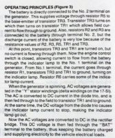
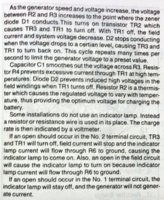
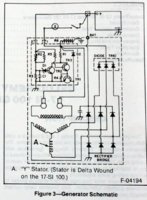
Those 3 extra diodes are called (in Delco-Remy lingo) the 'diode-trio'. They actually supply the power to the field (rotor), so that the alternator is self-powered.

On those ' idiot light' type regulators, when the ignition is first turned on, a little current passes thru the idiot light (it lights up), providing a little bootstrap current to the field (rotor). When the alternator spins up enuff to start producing power, the diode-trio also starts putting out more current to the field (rotor) to really get the alternator going. The voltage put out by the diode-trio stops current flow thru the idiot light, turning it off, calming the idiot's nerves.

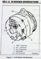
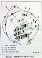
The Delco-Remy is a very common GM alternator, and the regulator design is quite a standard. Here's some excerpts that may be entertaining, or enlightening:

Delco-12SI-01.jpg Delco-12SI-02.jpg Delco-12SI-03.jpg Delco-12SI-04.jpg Delco-12SI-05.jpg Delco-12SI-06.jpg

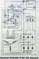
Here's the slightly simpler 10SI regulator schematic.
Same principle applies.

Delco-10SI.jpg
 
Thanks 2M. I am assuming that if the stator fails, there will no longer be current through the diode-trio and current will resume through the ignition. And the idiot light comes on again - at least you will know you have a problem.
 
... I am assuming that if the stator fails, there will no longer be current through the diode-trio and current will resume through the ignition. And the idiot light comes on again - at least you will know you have a problem.

Pretty much. There's several problem scenarios that can cause the alternator to stop output, the diode-trio starves, and the grounding side of the idiot light goes low, allowing it to light up. I rather like the design, as the self-powered aspect removes dependancy and voltage drops from a hot-lead power source, and the diode-trio can produce more voltage/power than that other way. The idiot light is handy, simple. But, it doesn't really tell you what's wrong, and there's some scenarios where it won't light during failure, like if the main rectifier pack malfunctions. For that, we'd turn on the radio (AM), dial to a blank station, and listen for alternator whine in the speakers. Really old-school stuff...
 
Last edited:
Here it is, the almost finished regulator/rectifier. I just need to reinforce the green plastic clamp. When I tied the Red B+ wire directly to the battery the regulator controlled at approx. 13.6Volts. I then tied the Red wire to the ignition Brown wire and it controlled at 14.2Volts (factory preset value) when measured at the battery. This weekend I will install this new regulator in the bike.

Regulator.jpg


It is not obvious from the photo but the regulator is isolated from the heat sink by a double layer of Mylar film running between the rectifier and regulator, passing underneath and up between the regulator and the aluminium fin. The Mylar film came from a photocopier over head projector sheet.

Thank you everyone for your assistance - It was an interesting learning experience for me.
 
The new regulator is now installed. Previously the old regulator started to control at 14.3 V and 2000 rpm. This new regulator is controlling at 14.2 V and 1500 rpm. This definitely is an improvement - Has anyone else observed an improvement like this with DIY rectifier/regulators?

Edit: After much searching and a bit of luck I have located a better regulator available in the UK. This is the Mobiletron VR-F114A and it is equivalent to the VRM794 as sold in the USA. The current price on Ebay in the UK is £9.50 + £4.50 p&p. Wiring is:

Red Wire - Ignition/Battery +
Green Wire - Field winding (Green wire to rotor brush on XS650SH)
Metal Case - Ground

Note: This regulator goes under many names so to find on Ebay search for "4475112" which is a Fiat Part Number.

Equivalents
BOSCH 0986192005
FIAT 4475112
FIAT 4721593
FIAT/MARELLI 4475112
FIAT/MARELLI 4721593
FIAT/MARELLI 581200260000
FIAT/MARELLI 64808106
FIAT/MARELLI 64808140
FIAT/MARELLI 64808143
FIAT/MARELLI RTT114A
LUCAS 21222081
LUCAS 21222106
LUCAS 21932004
LUCAS 581200260000
LUCAS UCB802
LUCAS UCB805
 
Last edited:
Finally got the chance to act on the advice given to me by Retiredgentleman, I stripped down the ignition switch as suggested. I cleaned, polished and lubed. I re-installed the switch and all its functionality now works and with no detectable voltage drop. I also put in a dedicated ground wire to a voltmeter so I now see the same voltage as at the battery, previously I saw 0.2Volts lower.
 
Someone mentioned these a month or two ago and I also noticed the Fiat type regulator. This A-Type regulator is the one you can find on Ebay by searching the Fiat Part Number "4475112". The heat sink is the ground connection unlike the regulator I used which has its casing as the connection to the fields winding. The rectifier/regulator is quite cheap to make in the USA and relatively cheap in UK - approx. £32 if you use a more expensive rectifier rather than those from China.
 
I find it hard to believe that the Fiat regulator was only used for two years and only on the Fiat. Most of the auto stores around me have it in stock, doesn't make sense, I never notice any Fiats on the road. I'm wiring one up for a Honda, have to remember the black and green ground wire difference between Honda and Yamaha, the green wire on the reg. has to change to black, and the ground wire from the body has to be green. I'm going to check on other vehicles that the Fiat reg. was used on, must be more. Oh yeah, they're usually $60-$70 in the stores.

Scott
 
I had to check, I checked at Napa, the 4475112 reg. was used on 6 different models of Fiats from '78-'83, about $32 from Napa but cheaper elsewhere and many offers of Chinese origin. Excuse me, sort of thinking out loud. Still doesn't make sense, why so many, why so available, why so moderately priced? Heck, you'd think these were for '60-'70 Chevy's.

Scott
 
Chinese origin for components like rectifier diode or other simmiliar it's not soo bad. You can get them cheaper and with good price aswell with compatibility and support.
 
Back
Top