Yamaha XS650 Experimental Clutch

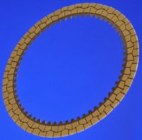
Barnett clutch plates arrived. It's been over 40 years since I've ordered plates from them. Newer Kevlar pads on them now. This oughta be interesting.
BarnettClutch01.jpg


I'm very happy about the tabs. Just the right width to properly fill the basket's slots. Other aftermarket plates I've examined have tabs that are several thousandths narrower, potential for plate rattle. And, the Barnett tabs are straight and smooth.
BarnettClutch02.jpg


Still waiting on more parts...
 
Doing research on the topic of "Wet clutch drag torque" yields an enormous amount of info. A really hot topic in the automotive automatic transmission arena. A lot of development work there, and interesting designs being introduced. The goals there are to reduce gas consumption and frictional heat in the transmission clutchpacks.

One item that caught my attention is this graph showing the relationship between clutch drag torque and the rpm differences of the plates in the disengaged clutch.
WetClutchDragTorque.jpg


Note the peak occurring around 500 rpms. Our XS650 clutch is reduction-driven by the primary gears. So, what do those numbers translate to at the engine?

The stock XS650 primary gearset is 27:72 = 2.667:1, giving these engine speeds:
Clutch rpm 500 ==> Engine rpm 1333
Clutch rpm 1500 ==> Engine rpm 4000
Clutch rpm 3000 ==> Engine rpm 8000

Interesting!
The max drag torque occurs near our normal idle speed of 1200 rpm.
No wonder neutral is difficult to get at idle.

Also of interest is that the drag torque minimizes at an engine speed of 4000 rpm.
This could explain why some members are able to get neutral when revving to around 4000 rpms.

Just for fun, what would this be when using the "High-ratio primary" gearset?

The Heiden "High Ratio" primary gearset is 35:80 = 2.286:1, giving these engine speeds:
Clutch rpm 500 ==> Engine rpm 1143
Clutch rpm 1500 ==> Engine rpm 3429
Clutch rpm 3000 ==> Engine rpm 6857

The "engine rev" trick should work at about 3500 rpms.
 
TorqueReduction.jpg

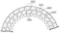
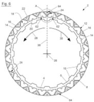
One promising area is in the design of various channels/grooves in the friction plate faces.
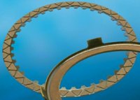
Much of our current crop of friction plates have simple radial grooves.
XS650ClutchPlates.jpg


According to the published research, it appears that significant reductions in drag can be achieved when those groove geometries introduce air, or 'aerate' the oil film between the plates during disengagement, the one time when 'foaming' is desired. Some of those alternate patterns out there are variating angles and hourglass shapes.
LowDragClutchPlates01.jpg LowDragClutchPlates02.jpg LowDragClutchPlates03.jpg LowDragClutchPlates05.jpg LowDragClutchPlates07.jpg

Might be worth looking into...
 
Last edited:
Awesome work, I knew that reving the engine and a stop and giving it a quick flick of the toe got her into neutral and now I know why.

Keep it coming.
 
Jus' saying a quick (enough to move the bike a couple inches) clutch release, pull back in, find neutral has been working for me on many motorcycles for decades. Not needed on a K1200LT.....
Kawasaki "solved" the problem with a second gear lock out when the bike's not moving, you can REEF up on the shifter from 1st, it will move ONLY to neutral, 2nd is blocked. Used on many of their bikes, I most recently found it on a Concours 14
"The GPz has a ball lockout system on the engagement dogs so that when the bike is at a standstill an upshift from 1st will ... The only disadvantage here is there's no way to engage 2nd gear for a bump start if the battery goes dead; the bike has to be rolling, engine running."
 
You guys are amazing.

I had never known that about the Kari 2nd gear lockout. Interesting.
 
I do like Gary does - release the clutch enough so the bike "tugs" ahead a little, pull it back in, attempt to find neutral again. Usually works.

So 2M, you're making parts again but exactly what? I can't imagine where a bunch of little screws and sleeves would go, what they would do.
 
...I can't imagine where a bunch of little screws and sleeves would go...

Hey, 5Twins! My greatest hope is that they don't end up in the oil filter.

...what they would do...

The version 1 clutch used a lot of fussy/fiddly/tweaky settings, trying to find the sweet spots. Now that I've determined those zones, for the way my clutch is setup, I can remove the fiddly/tweaky stuff and replace them with fixed dimension parts. It's still a bit fiddly, since I'm trying to hold dimensional tolerances to +0.0005/-0.0000. There's gotta be a better way...
 
An important part of this clutch project included a true-up/tune-up.

The clutchpack (7 friction and 6 steel discs) is sandwiched between the rear friction flange of the clutch boss (hub) and the pressure plate. If those two surfaces don't run true, there would be a loss of effective pressure plate separation. If the hub flange isn't true, the clutchpack will have to 'slant' a bit at final engagement. If the pressure plate isn't true, the dragging/feathering stage will linger while it settles into full engagement.

A DTI (Dial Test Indicator) and holding arrangement is needed for this. A good setup is this gooseneck adapter, as shown in 5Twins' pic.
PressPlate-5Twins.jpg


In my tests, I'm using the long 6mm shaft of an early steering damper, screwed into the closest upper sidecover screwhole in the engine case, with an indicator holder slide-adjusted on that shaft.

The first test showed significant runout (0.008" TIR) of the hub flange.

HubRunout01.jpg
 
The term "TIR" is often used with indicators, and can mean any combination of:
Total/True --- Indicated/Indicator --- Reading/Runout

For example, if the indicator swings fully between -0.003" and 0.005", that's a total of 0.008" of indicator travel, or an 0.008" TIR.

Note that this isn't the same as Tolerance. Tolerance implies a relative minimum and maximum to a specific value, as with wristpins.

The goal here is to achieve minimum TIR. This involves a bit of interpretation of the deviating needle, as some of the movement will be simple "wobble", and some may indicate surface undulations.

For example, while truing a rim, you may observe rim wobble, where the rim moves side-to-side synchronously with wheel rotation. Then you may also see a 'blip' in the indicator as the weld joint of the rim passes by. During wheel truing, the weld joint is ignored while the overall/general rim runout is adjusted.
 
To chase down this hub runout, removed the crank's primary drive gear, and the clutch's basket. Then reassembled the washers, spacer, washer, and hub. The hub nut must be torqued down to get proper readings. I was able to duplicate and confirm the 0.008" TIR.
HubRunout02.jpg


One particular area that would contribute to a true-running hub is the fitment of the 30mm sleeve and the final 2mm thick washer.

HubRunoutCause01.jpg


To achieve the best 'true' of that fitment area, find the best, undamaged surfaces of the (2) 2mm thick washers and spacer endface.
HubRunoutCause02.jpg


The two surfaces above show signs of damage, and would not be placed together at that critical zone.

Instead, these two surfaces are in great shape, and would be used.
HubRunoutCause03.jpg
 
I had marked the hub flange "H" and "L" for the high and low spots. A real close inspection of the hub's rear seating face revealed a tiny speck of imbedded metal, aligned with the "H" mark. Almost imperceptible, could barely feel it, easily overlooked. I was able to pick at it and pop it out.
HubRunoutCause04.jpg


Reassembly of the washers, spacer, and hub, TIR was now down to 0.002".
I decided that this was good 'nuff for this part of the true-up/tune-up.
 
The next part of the true-up/tune-up is getting the pressure plate to run true.

The first item to check is the "mushroom" pushrod, see if its face is square to its shaft. This mushroom shaft shows signs of running 'tilted' in its mainshaft bore. Note the scraping marks on the side of its shaft.
MushroomTrue01.jpg


That mushroom shaft showed significant runout on the lathe, so decided to use a different mushroom shaft in better shape. This one showed a TIR of only 0.001".
MushroomTrue02.jpg


A light facing pass trues it up to 0.000" TIR.
MushroomTrue03.jpg
 
The next item is the pressure plate. I removed the lathe chuck's jaws and fashioned-up some carriage bolts to slide into the jaw slots. Attached the pressure plate, with springs, to the chuck. Meticulous fiddling and shimming got the pressure plate to run as true as possible. I essentially shimmed-out the "wobble" component, noting significant surface undulations, of about 0.006". Double checked this "minimum wobble" setup by taking a reading on the pressure plate's center disc, where the "mushroom" fits. Found it to be running true, 0.000" TIR.
PressurePlateTrue01.jpg


So, now all I had to do was skim off the surface undulations. Very strange, high and low spots, as though the pressure plate was warped in wierd directions.
PressurePlateTrue02.jpg


You may be able to see the old and freshly cut surface better here.
PressurePlateTrue03.jpg


Finished the skim cuts, down to a TIR of 0.000".
This pressure plate is now as true as I can possibly get it.
 
Last edited:
Getting the pressure plate to run true in the assembled clutch is a rather tricky affair. There's (5) separate items that influence the true running of the pressure plate.

1- The square/true fitment of the mushroom pushrod (post #55).
2- The height of the (6) springscrew posts in the clutch hub.
3- The lengths of the (6) spring screws (or aftermarket sleeves)
4- The depths of the (6) spring seats in the pressure plate.
5- The (6) clutch springs, lengths and spring rates.

Item #2, the springscrew posts in the clutch hub. Hub on flat plate, depth indications of those posts showed a variance of 0.020" (0.5mm)!!!
HubPostHeight.jpg


Those posts had to be carefully ground down to get the heights equal.
 
Last edited:
Most of this stuff's over my head a bit, but it sure is an interesting thread. Out of curiosity it seems that 6 plates drag less than 7, so can I assume that it's because there will be more space available for plate separation? If so, maybe some sort of 5 plate setup would be better yet, with stiffer springs making up for the loss of engagement friction?
 
Hey, weaselbeak. A bit early, huh?

... Out of curiosity it seems that 6 plates drag less than 7, so can I assume that it's because there will be more space available for plate separation? If so, maybe some sort of 5 plate setup would be better yet, with stiffer springs making up for the loss of engagement friction?

Makes sense to me. I've experienced virtually zero drag from single-disc clutches. :D

But, in the case of the later 80-on clutches, using 6 frictions instead of 7, there's that "spring" disc at the rear of the hub. How much that thing moves is beyond me, I've never fussed with those. How much separation is consumed by that thing is an unknown...:shrug:
 
Back
Top