Yet another charging issue question !?

Terrible1

Fresh Meat
Messages
135
Reaction score
3
Points
18
Location
Vegas
I'm working with a 1973 tx650 motor that has points, ATU, battery, I am not charging the battery when riding around or when reving above 3k. The bike has just an early style 5 wire regulator with no tci. The bike is a kick start only and starts on first or second kick no problem. It even will idle no problem.

Following gggGarys thread here is what I found out. All readings were taken today with perfect 65 degree weather with a fluke 87 multimeter.

1. Battery is 12.5 v

2. Slap test does work but it is a very weak pull.

3. Jumper the green wire from the regulator and I DO NOT get 14.5 volts or anything close. Only 12.6 volts at best.

4. I have 12.4/12.3 on the brown wire at my ignition switch, and then the same at the positive brush terminal which is the black wire as mentioned in the trouble shooting guide.

5. Measuring the rotor resistance I get 5 ohms. Nothing when measuring rings to ground.

6. I'm unable to get this reading at the moment mostly because of the weather pack connector I have on the bike and the time here is 9 pm do the neighbors would be quite pissed at all the noise. I WILL TRY and get this tomorrow.

7. I get exactly .5 ohms on all three phases.

I'm unsure of the yellow write that should be capped off when running a solid state system but I will look into that now. The previous owner was the one who wired the bike this way and it seems that everything is correct. I DO HAVE the 3 plastic screw's on the brushes for a solid state regulated system.

I've been planning on a pma & pamco but wanted to ride the bike a little bit as I just got plate for it.

Anyone got any ideas? I'm open all suggestions!!! Thanks
 
If you have good voltage on the wire at the brushes, a 5 ohm rotor, I would suspect the brushes. The brushes are what carries the current to and from the rotor. If too short or too old they won't push against the rotor slip rings as hard as they should. This limits the strength of the magnetic field of the rotor. Old brushes can have the wire inside the spring broken.
The yellow wire is the voltage sensing wire the safety relay uses the know when the engine starts, then shutting the power to the starter relay off so the starter stops working. On the later models the safety relay also turned on the lights when the engine starts. So any voltage you read on there has no function for charging.
Leo
 
you say that you have no TCi in one sentence then later say that the bike has the early style regulator and rectifier ? which is it ?

If you have the early style Reg/Rect then you shouldn't need the plastic insulating screws on the stator connector because the rotor should be constantly grounded directly to chassis from the black wire in the 5xwire connector .

As I understand it it is the later setups (80 onwards) that use the TCi solid state rectifier/regulators that need the stator connector insulating because it is the TCi regulator that grounds the rotor depending on electrical load .

its a long time since I looked at this so someone please correct me if I am wrong about this .:wink2:
 
The TCI is the ignition and has nothing to do with the charging system. It is entirely possible that the PO has changed over to the later type of combo reg/rec without adding the TCI ignition. Pics of what you are working with will help greatly. Follow what xsLeo says as he is one the best resources for the stock charging systems on these bikes.
 
The later bikes do use a TCI but that's ignition not charging.
The later bikes used a solid state combined reg/rec. This is charging.
You can use the later combo reg/rec on the early bikes by ungrounding the one brush with nylon screws, and sending power to the black wire brush.
Don't get the TCI and charging confused, one has nothing to do with the other.
His bike came from the factory with the separate regulator and rectifier. In his set up the rectifier has 5 wires, three white, a red and a black, the regulator has three wires, one brown, one green, one black. My earlier response was thinking he was using a later style combo reg/rec.
In test #3 grounding the green wire only works with the 80 up combo reg/rec. This is the regulator bypass test.
The reg bypass test for the 70-79 bikes was different. You jumper from battery positive to the green wire.
Before we go further just what do you have for charging system parts?
Pics work well for IDing parts.
 
I have had the brushes off the bike last night and this morning. The springs are not broken and ate still pushing when installing the screws. I have just measured the brushes then selves and both if then are 16mm in length. Does anyone know what the new installed length may be? I'll take a gander in the clymer but that thing has hits n misses on info.

If it does turn out to be the brushes I'm going pamco no matter what. Hell ishould have gone pamco from the get go. Thanks XsLeo


If you have good voltage on the wire at the brushes, a 5 ohm rotor, I would suspect the brushes. The brushes are what carries the current to and from the rotor. If too short or too old they won't push against the rotor slip rings as hard as they should. This limits the strength of the magnetic field of the rotor. Old brushes can have the wire inside the spring broken.
The yellow wire is the voltage sensing wire the safety relay uses the know when the engine starts, then shutting the power to the starter relay off so the starter stops working. On the later models the safety relay also turned on the lights when the engine starts. So any voltage you read on there has no function for charging.
Leo
 
Yes this is what the previous owner I think did. I've got some pictures on my phone that I'm going to upload now but it may sound like I need to run the bypass regulator check for the 70-79 year like excess Leo said.

Hopefully the pictures will clear anything up. I see in your post Leo that you say separate regulator and rectifier, is that two units? I only have one "box"

Thanks again guys

The TCI is the ignition and has nothing to do with the charging system. It is entirely possible that the PO has changed over to the later type of combo reg/rec without adding the TCI ignition. Pics of what you are working with will help greatly. Follow what xsLeo says as he is one the best resources for the stock charging systems on these bikes.

The later bikes do use a TCI but that's ignition not charging.
The later bikes used a solid state combined reg/rec. This is charging.
You can use the later combo reg/rec on the early bikes by ungrounding the one brush with nylon screws, and sending power to the black wire brush.
Don't get the TCI and charging confused, one has nothing to do with the other.
His bike came from the factory with the separate regulator and rectifier. In his set up the rectifier has 5 wires, three white, a red and a black, the regulator has three wires, one brown, one green, one black. My earlier response was thinking he was using a later style combo reg/rec.
In test #3 grounding the green wire only works with the 80 up combo reg/rec. This is the regulator bypass test.
The reg bypass test for the 70-79 bikes was different. You jumper from battery positive to the green wire.
Before we go further just what do you have for charging system parts?
Pics work well for IDing parts.
 
Fs2iQKR.jpg


That is the only box on bike.

I also did find a tolerance for the brushes and the manual says replace when at 7mm so I think I'm good there.
 
Ok, That looks to be an 80 up combo reg/rec. Hard to say just by the look.
What I might try is unhooking the wires from the both brushes. Hook up a jumper from battery positive to the green wire brush, Start the bike hook up the meter, jumper from the other brush to ground. Does this change the battery voltage?
Leo

Yep. This was it. Getting 13.8 - 14.2 at idle. So my regulator is shot? :thumbsup:

So this means I have a 80 combo regulator correct? Do I have the wiring backwards by chance!?

Thanks a bunch!
 
Last edited:
I just rechecked my wiring. I currently have positive voltage on both brushes. Is this correct? I wouldnt think so since I just jumpered the green to positive and black to ground and it began to charge.
 
Probably.
Did you wire this bike? or did you get it this way?
Either way you need to check a few things. To use an 80 up reg/rec on the 70-79 bikes you need to replace the three steel screws that hold the black wire brush with nylon screws. This isolates that brush from ground.
You need to run power from after the main switch to this black wire brush.
When wiring in the 80 up reg/rec hook the green wire to the green wire brush. the brown wire to power after the main switch. I would run the brown power wire to the brush over to the reg/rec then splice this wire to the brown wire feeding the reg/rec. Then from this splice to power after the switch. This simplifies things a bit.
The rest of the wires on the reg/rec three white to three white from stator, black to ground, red to battery positive.
Try this set up first.
If you find it still won't charge, you can try another 80 style reg/rec, buy a solid state reg/rec of the 70-79 style, this won't need the three screw mod, it hooks up as the 70-79 stock units.
There are also a couple other alternatives. I have my 75 set up to use the 80 style reg/rec but use a reg from a 75 Dodge dart. Or most any Chrysler product from about that year up to about 80. Can be found at most part stores for under $20.
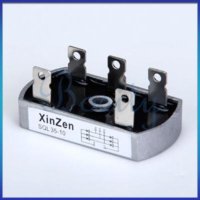
Get a three phase rectifier off Ebay for around $5.
There is also a Jeep version of a reg that works like the 70-79 bikes. I don't recall which Jeep but it was when AMC built them.
There are several threads talking about just how to wire them in.
I have pics of the units I used. First pic is the Ebay rectifier, rating1000 volts 25 amps. Plenty for the XS650. The second is the reg.
Leo
 

Attachments

  • $(KGrHqR,!jQE5cFUs8ftBOepe(8)4!~~60_1.jpg
    $(KGrHqR,!jQE5cFUs8ftBOepe(8)4!~~60_1.jpg
    16.1 KB · Views: 251
  • 51168.jpg
    51168.jpg
    2 KB · Views: 300
The later bikes do use a TCI but that's ignition not charging.
The later bikes used a solid state combined reg/rec. This is charging.
.

yeah of course it is doh!....thanks Leo. :wink2: I'm mixing up the TCi with the later solid state rect/regulator. I'm a bit out of touch these days to be honest.

The point I was making was still valid however as it read to me like he was using an early style seperate rect/regulator but insulating his stator ground connection which would not be correct . There was some confusion over whether he was using an early pattern rect/reg or a late type solid state one. I was just trying to clear that up
 
Well I received the bike with the parts on it but the wiring was less than acceptable. I rewired it using one of the 80 wiring diagram that is in the diagram thread.

The screw's are nylon.

I will try the rewiring and see what happens.

12v to black brush
Green wire from regulator to green wire on other brush
Power wire to brown wire in regulator and jumper to green brush

Is that correct? I got a little lost on your description of the brown wire and brush jumper part.

I will start to look into the other solid-state regulator options. Like always thank you very much.


Probably.
Did you wire this bike? or did you get it this way?
Either way you need to check a few things. To use an 80 up reg/rec on the 70-79 bikes you need to replace the three steel screws that hold the black wire brush with nylon screws. This isolates that brush from ground.
You need to run power from after the main switch to this black wire brush.
When wiring in the 80 up reg/rec hook the green wire to the green wire brush. the brown wire to power after the main switch. I would run the brown power wire to the brush over to the reg/rec then splice this wire to the brown wire feeding the reg/rec. Then from this splice to power after the switch. This simplifies things a bit.
The rest of the wires on the reg/rec three white to three white from stator, black to ground, red to battery positive.
Try this set up first.
If you find it still won't charge, you can try another 80 style reg/rec, buy a solid state reg/rec of the 70-79 style, this won't need the three screw mod, it hooks up as the 70-79 stock units.
There are also a couple other alternatives. I have my 75 set up to use the 80 style reg/rec but use a reg from a 75 Dodge dart. Or most any Chrysler product from about that year up to about 80. Can be found at most part stores for under $20.
Get a three phase rectifier off Ebay for around $5.
There is also a Jeep version of a reg that works like the 70-79 bikes. I don't recall which Jeep but it was when AMC built them.
There are several threads talking about just how to wire them in.
I have pics of the units I used. First pic is the Ebay rectifier, rating1000 volts 25 amps. Plenty for the XS650. The second is the reg.
Leo
 
its much easier to follow a proper wiring schematic than simply joining coloured wires together with no understanding of how things connect and work.
This is particularly so when the previous owner has hacked the wiring and none of us know what he has done.

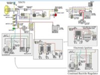
If you look at the schematic below the wiring schematic shown is of a typical early XS650 like yours that has been simplified. It has seperate rectifier and regulator shown in the shaded box lower left .
That is standard for your bike.

The PO has apparently modified the wiring and fitted a later type rectifier/regulator from a 1980+ bike . This has a combined rectifier and regulater in a alu box . This solid state rect/reg operates the charging system differently than the earlier sytem but essentially they do the same thing.

All you need to do is take the shaded schematic lower right (labeled combined rectifier /regulator) and superimpose it diectly on top of the early version shaded box (lower left) and you have your bike.

You must insulate the brush assembly with plastic screws because the later rect/reg grounds the green wire from the rotor brush differently via the combined rect/reg

You can see that whoever drew the schematics did so for owners wishing to upgrade their early charging systems with the late style combined rect/regulator so that the wires connect up exactly to the same points
 

Attachments

  • charging schematics.jpg
    charging schematics.jpg
    241.2 KB · Views: 274
Last edited:
Thank you very much for the diagram. This does clear a few things up.

Currently my bike is wired like the layover schematic on the early wiring diagram. I'm starting to think that my combo regulator/rectifier is in fact shot. I will continue on with the wiring check that xsleo suggested and report back when I get some results.

Thank you again guys. Hopefully this these wool help some others figure out some issues too. :bike:

its much easier to follow a proper wiring schematic than simply joining coloured wires together with no understanding of how things connect and work.
This is particularly so when the previous owner has hacked the wiring and none of us know what he has done.

If you look at the schematic below the wiring schematic shown is of a typical early XS650 like yours that has been simplified. It has seperate rectifier and regulator shown in the shaded box lower left .
That is standard for your bike.

The PO has apparently modified the wiring and fitted a later type rectifier/regulator from a 1980+ bike . This has a combined rectifier and regulater in a alu box . This solid state rect/reg operates the charging system differently than the earlier sytem but essentially they do the same thing.

All you need to do is take the shaded schematic lower right (labeled combined rectifier /regulator) and superimpose it diectly on top of the early version shaded box (lower left) and you have your bike.

You must insulate the brush assembly with plastic screws because the later rect/reg grounds the green wire from the rotor brush differently via the combined rect/reg

You can see that whoever drew the schematics did so for owners wishing to upgrade their early charging systems with the late style combined rect/regulator so that the wires connect up exactly to the same points
 
Ok, wire it up as I suggested, as that diagram shows. Power to the black wire brush, green to green, Power to the brown wire of the reg/rec. No jumpers. You did the jumper test and got a charge. Now doing this wiring, if your reg/rec is good it should charge. If not It sounds like time to replace.
There are threads around further describing the Chrysler reg a Radio Shack rectifier replacement, The same rectifier will work with the Jeep regulator.
The Ebay three phase rectifier is about the same price but the wiring is a bit more simple.
The Jeep reg is a square box with four wires, you wire it up a bit differently than the Chrysler reg but it doesn't need the nylon screw mod.
Either one is a good mod. Not hard to do and much more efficient than the old stuff. Very reliable too.
The Reg I used came with a one year warranty, so if it craps out in a year, just return it for a new one. Just don't loose the receipt.
I have used the Radio Shack rectifier, works very well. I have a couple of the Ebay rectifiers on hand for spares.
Leo
 
Well after trying what you suggested xsleo it does look like the regulator is shot. I've wanted to go pamco\pma since I found out about them but only if the stock stuff went bad. I'm going to make a Dustin over the next few days

Once again thank you xsleo n peanut. I appreciate your help a bunch.
 
Back
Top