sleddog83
XS650 Addict
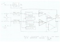
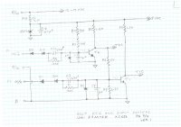
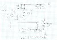
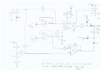
Here are some rough schematics of a 12-01 igniter board (1980). This is the first version and a rough draft, but will give you something to chew on. The block is guess work. Pages 2 and 3, I believe to be reasonably accurate at this point in time. I have some doubts about page 4.
The general theory of the board is this: The pulses from the pickup modules I labelled as P1, (the first pulse ) and P2 (etc). Both are inverted through input transistors T1 and T2. The signals off of the transistor collectors I call T1C and T2C go to multiple places on the board, especially T2C. The pulses are positive going, but I think the trailing edges of the pulses are more significant. These pulses turn on integrator circuits using R22, R23 T6 and C15 and R14, R51, T4 and C12. The ramps produced by these circuits are reset by differentiator circuits. The ramps produced by the two integrators go through two unity-gain op-amps c and d. They are then compared at op-amp a. I am not sure how op-amp b fits in at this time.
I will need to scope this a bit more on the bench to firm this up.