XS650 Clutch Worm Mod (rebent arm) testing

TwoManyXS1Bs

BBQ Hunter
Top Contributor
Messages
14,670
Reaction score
15,290
Points
813
Location
Fredericksburg, Texas
This is a followup/companion piece to the Clutch Worm experiment thread:

http://www.xs650.com/forum/showthread.php?t=31554

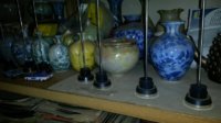
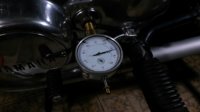
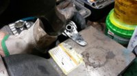
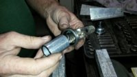
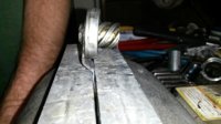
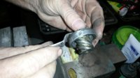
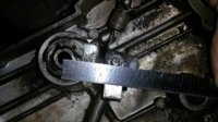
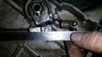
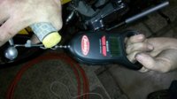
Spent last Friday (the 13th!) with DogBunny, performing and evaluating the rebent clutch worm arm mod. There's no shortage of XS650s and parts here, in fact DogBunny's place could best be described as an eclectic mix of thermometer dipsticks (pic #1), a pottery and fine ceramics studio (backround of pic #1), and '447' XS650 man cave. A talented ceramics artisan lives here, the ceramics in the pic representing only a small sample of this studio. The 'XS bug' is strong here. I can finally say that I've personally observed more than one XS650 in one place (actually several).

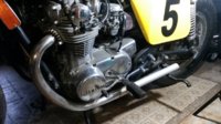
The testing was done on two bikes. The first was a 'Yellow Tracker', with a somewhat stiff clutch action. The second on DogBunny's daily rider, with a black/red polka-dot/ladybug paint scheme. All the bikes here are later '447' types, with a couple of clutch configuration differences to my stock '256' type XS1B. First, these all use the two-piece clutch pushrod. Second, the clutch cables are routed differently, outside the carbs, left of the left carb.

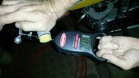
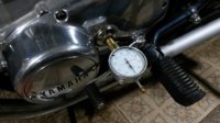
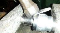
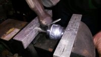
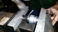
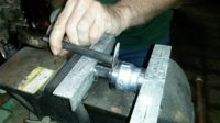
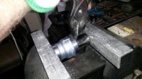
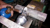
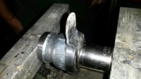
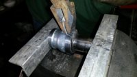
The plan is to perform the rebend mod only, isolating its influence. Notes and pics will be taken of the 'before' configuration', then Dogbunny will perform the mod using the supplied tools. I'll be helicopter-hovering with the smartphone camera. Then get notes and pics of the 'after' configuration.

This will confirm whether this mod can be successfully performed in the field, and what benefits, if any, are achieved with the mod.

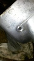
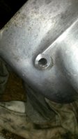
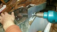
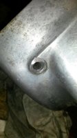
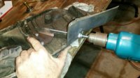
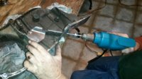
Separately, DogBunny will perform the sidecover cable entry hole mod on a spare sidecover, evaluating the cutting tool. This particular mod will not be done on the two test bikes, as the cables are routed differently, and the perceived benefit of this is unknown.

I have 86 pics to organize/weed/sort, so this thread will be posted in clumps as each section is done.
 

Attachments

  • ThermoDipSticks.jpg
    ThermoDipSticks.jpg
    139.8 KB · Views: 653
I believe I can speak for the entire XS650 community in that we are anxiously awaiting the results of the tough clutch fix saga. Thanks for all your work guy's. ---tim
 
Yes, this is one of the last areas of the XS I haven't had any luck improving. I've tried all the recommended upgrades (long rod, improved hub bearing, etc.) with little to no improvement. I never did buy a whole new worm gear but have tried 4 or 5 different used ones and all worked the same. I even mixed and matched males and females from my stash with no better results. I will be trying this come spring. At the moment I sit here staring out my window at over a foot of snow, lol.
 
Pic #1 - The first bike to be tested, the 'Yella Tracker', has the clutch cable routed outside the carbs, up under the tank, crossing thru to the right side, and coming up thru the instruments to the clutch lever. There is a significant kink where the cable passes thru the instrument cluster, and the clutch feel is stiff/strained. The bike is fitted with a low crossbarred motocross handlebar, and DogBunny says that the clutch cable may be a bit long, he's had routing problems with it. The clutch lever is a fast-pull type, with a longer than stock pivot-to-cable-end distance of 1.1", stock being about 1". We'll not fool with the cable, we want an apples-to-apples comparison of the clutch worm mod only.

Pic #2 - Mid-range pull tests ranged from the 17's to 19 lbs.
 

Attachments

  • DBike1A01.jpg
    DBike1A01.jpg
    168.9 KB · Views: 620
  • DBike1A02.jpg
    DBike1A02.jpg
    123.2 KB · Views: 605
Pic #1 - The dial guage is fitted to the sidecover and zeroed.

Pic #2 - The dial guage rotates counter-clockwise as the clutch is pulled, passes 'zero' for 0.050" travel, adding another 0.014", for a total of 0.064" of plunge travel.
 

Attachments

  • DBike1A03.jpg
    DBike1A03.jpg
    138 KB · Views: 697
  • DBike1A04.jpg
    DBike1A04.jpg
    97.6 KB · Views: 533
Pic#1 - The sidecover is pulled and the clevis hole location is measured with the cable still attached. Here, the 3.7" measurement shows that the cable is far too short, the worm lever will be falling into the less-advantageous zone upon being pulled. An extra 1/2" of cable length is needed here. But, we'll see how the mod handles this.

Pic #2 - The clevis pin 'Start' distance is measured. This 'start' point is where the worm begins to displace laterally from the arm's fully retracted forward position. This measurement is 4.3", so a 1/2" longer cable will function well here.

Pic #3 - Then the worm arm distance (worm center to clevis pin) is measured, here it shows 1.35".
 

Attachments

  • DBike1A07.jpg
    DBike1A07.jpg
    175.1 KB · Views: 648
  • DBike1A06.jpg
    DBike1A06.jpg
    195 KB · Views: 621
  • DBike1A05.jpg
    DBike1A05.jpg
    204.7 KB · Views: 667
A foot of snow! Yeah, I remember those days, living in the fingerlakes. Displaced Texans get cabin fever quickly up there.

Caught a bug from the Austin trip, so the posts will be coming a little slower, depending on the speed of Nyquil...
 
TwoMany, great write up so far, we all really appreciate your work on this.
Since I was the guinea pig, I will be filling in at times. I don't want to spoil the story, but will say now that today was nice, did quite a bit of riding on the Bug Killer, that was the second bike that I modded using TwoMany's jigs and guidance, and all was fine.
I'll also reiterate something that TwoMany already said: I always route the clutch cable to the left of the left-hand carb. I have always thought that this was a smoother routing -- I do it to every XS650 that touches my hands. I was actually a little surprised to learn that the factory routed the cable between the two carbs. Anyways, right or wrong, good or bad, that's how the 2 bikes in this test write-up are set up.
 
Bending the worm arm:

During this process, many pics were taken of DogBunny performing the mod. After a couple of 'oops' and 'lemme try this', he came up with a method that works for him. The pics are rearranged to depict his method, and will show some detail anomalies. I believe the movie studios call this 'continuity', and movie buffs delight in finding the inconsistancies in scene-to-scene. So, please don't get confused because a part looks slightly different pic-to-pic.

Pic #1 - First, remove the grease seal, adjuster screw, and clean the worm unit.

Pic #2 - Next step is to flatten the arm, a little heat is used here.

Pic #3 - Place the arm on an anvil.

Pic #4 - And the arm is beaten flat.
 

Attachments

  • DBike1B04.jpg
    DBike1B04.jpg
    169.4 KB · Views: 675
  • DBike1B03.jpg
    DBike1B03.jpg
    139.5 KB · Views: 713
  • DBike1B02.jpg
    DBike1B02.jpg
    178.4 KB · Views: 664
  • DBike1B01.jpg
    DBike1B01.jpg
    128.5 KB · Views: 687
Pic #1 - The worm protector is slid onto the worm.

Pic #2 - The sealcup protector is slid onto the sealcup, forming ramp aligned under the arm.

Pic #3 - A socket is chosen (3/4" 6-pt) that fits over and sandwiches the arm, and clears the tack welds.

Pic #4 - Hold the whole worm/clampjig with one hand while clamping in the vise.

Best to use softjaws, like the 1" aluminum angle pieces here, avoids damaging the clampjigs and socket. Double check that the assembly is centered in the jaws, and the arm is centered over the forming ramp. Cinch down the vise quite snugly, but not to the point of deformation.
 

Attachments

  • DBike1B05.jpg
    DBike1B05.jpg
    134.1 KB · Views: 607
  • DBike1B06.jpg
    DBike1B06.jpg
    95.4 KB · Views: 605
  • DBike1B07.jpg
    DBike1B07.jpg
    108.3 KB · Views: 610
  • DBike1B08.jpg
    DBike1B08.jpg
    178.2 KB · Views: 614
The first bend:

Pic #1 - A little heat is applied to the arm base.

Pic #2 - Pliers start the bending.

Pic #3 - A broad punch keeps the bend close to the forming angle.

Pic #4 - Then beat into submission with a hammer (double-check vise tightness).

Pic #5 - Keep the bend tight against the forming angle.

Pic #6 - Ensure the bend makes at least a 45° angle.
 

Attachments

  • DBike1B14.jpg
    DBike1B14.jpg
    139 KB · Views: 552
  • DBike1B13.jpg
    DBike1B13.jpg
    120.4 KB · Views: 541
  • DBike1B12.jpg
    DBike1B12.jpg
    152.9 KB · Views: 539
  • DBike1B11.jpg
    DBike1B11.jpg
    152 KB · Views: 540
  • DBike1B10.jpg
    DBike1B10.jpg
    152.8 KB · Views: 544
  • DBike1B09.jpg
    DBike1B09.jpg
    152.2 KB · Views: 546
The second bend:

Pic #1 - Bent arm, ready for the next bend.

Pic #2 - Mark a line, starting from the return spring hole, or near it (keeping above the reference notch in the forming angle). Draw to the left, angling upward about 8°. This allows doing the bend and twist in one step.

Pic #3 - Apply some heat, and start the bend with pliers with broad/shallow jaws.

Pic #4 - Continue bending, following the guide line.

Pic #5 - Good enough using the pliers.
 

Attachments

  • DBike1B19.jpg
    DBike1B19.jpg
    139.7 KB · Views: 594
  • DBike1B18.jpg
    DBike1B18.jpg
    147.3 KB · Views: 540
  • DBike1B17.jpg
    DBike1B17.jpg
    164.9 KB · Views: 547
  • DBike1B16.jpg
    DBike1B16.jpg
    170.7 KB · Views: 532
  • DBike1B15.jpg
    DBike1B15.jpg
    146.9 KB · Views: 529
Again great pics and write up, thanks.---tim
 
Neat stuff goin' on here guys.

My favorite tool for bending stuff like this is a big adjustable wrench (Crescent wrench) because the jaws don't spread. Just tighten the jaws down on the plate to be bent. I use pliers too but on heavier stock the jaws spread and I don't get much control.

Tom
 
Finishing the second bend:

Pic #1 - Remove the worm assemblage from the vise, and flatten the arm extension on the anvil.

Pic #2 - Ensure that the area near the clevis pin is flat, and that the clevis will be able to sweep its angle without interference to the arm bend.

Pic #3 - Fit the arm extension fully into the vise. Clamp down to flatten it.

Pic #4 - Check that the arm extension is perpendicular to the worm drive.

Pic #5 - Straighten as necessary. Ensure that the arm has the 8° twist.
 

Attachments

  • DBike1B25.jpg
    DBike1B25.jpg
    86.3 KB · Views: 543
  • DBike1B24.jpg
    DBike1B24.jpg
    134.3 KB · Views: 566
  • DBike1B23.jpg
    DBike1B23.jpg
    152.6 KB · Views: 552
  • DBike1B22.jpg
    DBike1B22.jpg
    159.9 KB · Views: 526
  • DBike1B21.jpg
    DBike1B21.jpg
    105.6 KB · Views: 554
Pic #1 - Completed rebend mod. Now inspect worm drive threads for damage.

Pic #2 - Most common problem is where the threads' sharp leading edges get bent and/or nicked. Gently file these leading edges down to remove nicks/burrs, and sharpness. Don't want these to cut the nylon worm body.
 

Attachments

  • DBike1B26.jpg
    DBike1B26.jpg
    126.9 KB · Views: 538
  • DBike1B27.jpg
    DBike1B27.jpg
    108.4 KB · Views: 547
Recutting the angle of the clutch cable seat at the cable entry hole would be the next step in this mod. Since DogBunny's bikes have the clutch cables routed outside the carbs, modifying his sidecovers for the new entry angle was bypassed. However, using my spare sidecover, DogBunny performed this mod using the fabricated casecutter.

The pilotguide alignment plate is attached to the two worm body screw holes. The piloted casecutter is inserted into the power drill. Three flats on the driveshaft fit into the jaws.

Pic #1 - The piloted casecutter is inserted into the clutch cable entry hole, tip of the pilot fits into the guide

Pic #2 - An initial cut is made.

Pic #3 - Progress of the cutting action. You can see the new angle appearing

Pic #4 - More cutting.

Pic #5 - Another inspection, almost there. Only about 1/16" total will be removed, so progress slowly.

Pic #6 - Last cut, finished.
 

Attachments

  • CaseCut06.jpg
    CaseCut06.jpg
    123.7 KB · Views: 539
  • CaseCut05.jpg
    CaseCut05.jpg
    138.4 KB · Views: 538
  • CaseCut04.jpg
    CaseCut04.jpg
    162.8 KB · Views: 542
  • CaseCut03.jpg
    CaseCut03.jpg
    142.8 KB · Views: 558
  • CaseCut02.jpg
    CaseCut02.jpg
    150.6 KB · Views: 552
  • CaseCut01.jpg
    CaseCut01.jpg
    159.8 KB · Views: 556
First bike, test results:

Pic #1 - The modified worm is reassembled into the sidecover. Arm length measurement is 1.3"

Pic #2 - The clevis pin 'Start' distance is 4.4". The installed cable length is 3.7", short, same as before.

Pic #3 - Pull tests showed 17 lbs at mid range, no significant improvement here.

Not shown, the actuator plunge travel was 0.061", a slight loss from the original 0.064".

So the improvement here is zero, zilch, zip, nada.

I believe that a longer inner cable and re-routing would yield improvements on this particular bike, but that's not part of this test. DogBunny decided to try the mod a second time on his daily rider, the polka-dot bug killer. That report will follow.
 

Attachments

  • DBike1C01.jpg
    DBike1C01.jpg
    177 KB · Views: 492
  • DBike1C02.jpg
    DBike1C02.jpg
    169.1 KB · Views: 466
  • DBike1C03.jpg
    DBike1C03.jpg
    127.2 KB · Views: 498
Back
Top