Alternator Disable Mod.

Jim

Beyond the edge is the unknown. Here be Dragons
Top Contributor
XS650.com Supporter
Messages
16,517
Reaction score
67,277
Points
813
Location
Kansas City Mo.
One of the things I've never liked about the XS is the fact that the alternator is energized as soon as you turn the key on. Another dislike of mine is the way the headlight is turned on. Here's whats happening.....
The ignition switch (hereafter just called the iggy sw.) supplies power to the fuse box. The fuse box in turn sends 12v to the regulator. The engine's not running yet, so the alternator isn't producing any power.... 0 volts. The regulator... bless it's heart, is just a dumb box. All it see's is a low voltage condition. Wanting to balance the equation, it sends all the power it can to the rotor to increase it's field strength, trying to get the alternator to put out about 14v...... which it can't do because.... well, the engines not running yet.

That current draw from the regulator and rotor comes out to about 2.5 to 3 amps. Don't sound like much, but lets face it.... the XS starter ain't exactly a world class powerhouse. Add to that a marginal or weak battery.... and the ol' 'lectric leg has to work hard to get it's job done. that 2.5-3 amps could be better spent helping the starter instead of fighting it.

And fight it... it most certainly does. That lost power is used to energize the rotors magnetic field, which now has to spin inside the stator. It ain't much, but that's extra horsepower the starter has to supply to overcome the magnetic field and spin the engine.

I ain't an engineer, so I honestly can't tell you how much power that field robs from the starter... but ANY power loss seems counter-intuitive in my mind. Why make the starter work harder when we don't have to? We don't need the alternator yet, so why in hell are we turning it on? Makes no sense.

Another problem is the way the lights are turned on. The alternator output is also sent to the safety relay on the single yellow wire. As soon as the safety relay sees an output from the alternator, it latches and turns the lights on. And we've all had this happen.... we hit the start button, the engine spins over, fires once or twice and then dies. The alternator generates just enough power to latch the safety relay and now the lights are on. We are now robbing even more power from the battery just when we need it for the starter. Why?

So, here's the solution.... we interrupt power to the regulator during start with a normally closed (NC) relay.
Like this....

Alt bypass.png

The 12v from the fuse box normally goes straight to the reg./rec. powering the alternator. Instead, we route that power to the "Alt Disable Relay".... (ADR). Power goes through the contacts to the reg. when the bike is running. During start, the 12v from the starter solenoid is (also) sent to the ADR coil which opens the contacts and shuts off the regulator.... which in turn, shuts off the alternator. Now there is no power being lost and no additional load (from the magnetic field) on the starter.

As soon as the engines starts, we release the starter button, the relay closes, the alternator comes to life and the lights come on. It's such a simple mod I can't understand why Yamaha didn't just include the relay when they built the bike.

My original plan was to incorporate this mod into the SG and then put up some quantifiable results. Right now I'm laid up and unable to work on the bike.... and bored to friggin tears. Writing this gives me something to do and an idea for you guys to chew over. If anyone's interested in trying this I'll add the part no. of the relay I'm using and my thoughts on where to tie into the existing wiring.
Cheers.


*** The brown wire from the ADR runs just to the regulator on 70-79 bikes. It splits and runs to the Reg/rec and the rotor (brush) on 80 and up bikes.
 
Last edited:
Smart...Simple, looks easy.

Aussie Bikes have the on/off switch on the Oceania models right up until the end of production in 81

One thing that has always bugged me when people have a car/bike or any vehicle and it wont start on the first or second third or forth wind over.........They keep winding the engine over untill the battery is starting to die.............then they will try again in a few seconds and you can hear the battery is struggling and they again wind the engine over 3, 4, 5 or more times until the battery either wont turn the engine over or near enough to..........

When living in NZ i was in Taranaki under the mountain. Gets cold, slight sprinkling of snow every 5 years or so but plenty of frosts and some sleet in the winter........gets down to minus 5, 10 with the chill factor.........

83 Canadian XS with factory TCI. Now i can't say i was 100% with my maintenance but would keep the battery charged and connections clean. The light on was something i had to learn to get used to. ............

1;.......1st start in the morning, (Summer), I would never let the bike turn over more than 4 times using the starter motor. If the bike didn't start after 4 revolutions, instant key off.................... Wait for at least 30 seconds............Why???.......let the battery generate some surface charge...........Key on and hit the button again.........90% of the time it would start before the forth time the engine turned over...........

Never would i try to crank over the engine more than 4 times using the starter button.........

In the winter the bike would be in the shed but cold. Try the starter button eah.......eeaaahhh.........that an't going to start.......on a sunny winters day i would wheel the bike out into the sun sheltered from the breeze and let it sit for 30min or more and the bike would be warmed up and the battery would be strong enough to start the bike using the procedure 1 above.............

I never let the battery get drained enough from using the starter motor that i couldn't kick start the bike if needed..........
 
Last edited:
Jim,

I like where you are going with this, and think I'll incorporate this setup on my '81 H. I think switching the relay off the starter solenoid output is smart, but I think I would not want to interrupt the voltage sensing wire for the regulator, or more precisely, would not want to introduce additional resistance to the voltage sensing wire.

I know the brown wire you are interrupting is the wire that switches the regulator on, but can someone confirm that it's not also the voltage sensing wire? The sensing wire has to be this brown one, or the red one going straight to the battery. Can someone tell me which wire is the battery voltage sensing wire?

-Mark (my first comment here!)
 
Whilst i think the debate is certainly valid and the idea of added relay is a good one, i shan't be incorporating it into mine, as sometimes we just over think things and just add more complexity into the situation which by a long shot is what happened when yamaha put these wiring systems into place, i have removed some of the clutter out of my system which also lightens load on the needed parts.
 
Yes, '78 was the last year for the switch on the U.S. models but it was somewhat "neutered" on this model because '78 was also the first year for the headlight auto-on relay. The switch only functioned with the key on, motor not running. Once you started the bike, the auto-on relay kicked in and turned the headlight on, regardless of what position the handlebar switch was in. Pretty silly set-up in my opinion.
 
Wow... forgot about this thread.:doh:
I've updated the schematic in the first comment. Added the brown wire from the splice at the reg/rec to the rotor so that relay also kills power to the rotor.
The results of this mod are mixed. With a good electrical system and a good, fully charged battery, there's no noticeable benefit to this mod as far as starting the bike goes. I suspect that with a weak battery, it would help. Charging or replacing the battery would also help in that case. :rolleyes:
There is one side benefit to this mod, it inhibits the headlight during start. You know... the engine pops a few times and dies, but that's enough to trip the light relay and turn the headlight on. Then, unless you cycle the key off and back on, any subsequent start attempt has the added drain of the headlight. This mod does prevent that. For that reason, I left it installed. I feel that benefit is worth having it.
Would I do this mod just for the headlight benefit? To be honest, I'm not sure... but since it's already there, I've left it in place.
 
Last edited:
Jim,

I like where you are going with this, and think I'll incorporate this setup on my '81 H. I think switching the relay off the starter solenoid output is smart, but I think I would not want to interrupt the voltage sensing wire for the regulator, or more precisely, would not want to introduce additional resistance to the voltage sensing wire.

I know the brown wire you are interrupting is the wire that switches the regulator on, but can someone confirm that it's not also the voltage sensing wire? The sensing wire has to be this brown one, or the red one going straight to the battery. Can someone tell me which wire is the battery voltage sensing wire?

-Mark (my first comment here!)
Hi Mark... and welcome to the forum!!
Yes, the brown is the voltage sensing line and no... running it through a relay doesn't add any resistance to it. All it's doing is shutting it off, just as you would with the key. After I installed the mod, I discovered that shutting down the regulator didn't kill the rotor. Apparently the green, ground switching wire defaults to ground when power is removed from the regulator. So, you also have to remove power from the rotor. I've changed the schematic to reflect that.
 
Yes, '78 was the last year for the switch on the U.S. models but it was somewhat "neutered" on this model because '78 was also the first year for the headlight auto-on relay. The switch only functioned with the key on, motor not running. Once you started the bike, the auto-on relay kicked in and turned the headlight on, regardless of what position the handlebar switch was in. Pretty silly set-up in my opinion.
That's interesting. I had no idea. I remember when the gov't made us turn the lights on. It seems it was '76 or '77.
 
Yes, it was in the late '70s sometime. My brother's buddy had a brand new late '70s/early '80s Suzuki 550 four. The headlight came on with the key and was always on, but it still had the on-off switch on the bars. You just couldn't move it from the "On" position. Turns out all Suzuki did was stick an extra plastic part in the switch housing to block the on-off switch from moving. We took it out and the switch moved and worked normally again.
 
Thanks for the quick response! I'm planning a bobber/rat but want to retain electric start. I've sourced a couple little tiny AGM batteries that are rated at 55cca each (Zuma scooter batteries) running them in parallel I'm hoping to have 100cca, so I'll be conserving as much power at startup as possible! I'll need the lighting and the field windings off when starting for sure! So, I'll interrupt the field directly.
 
I recently got a new laptop, breaking it in, used up my web data allotment for the month.
Now I can put in my 2 cents worth, using this new-fangled laptop.

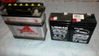
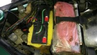
I wanted to pursue an automatic alternator/rotor disabler during startup. Having an XS1B means having a small battery. Mine's a pair of 6v, 4.5ah deer feeder batteries tied in series.
2x6vBattery1.jpg 2x6vBattery2.jpg

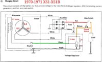
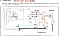
This schematic depicts the typical 70-79 charging system, with the mechanical relay-type regulator.
70-71_XS1-XS1B_ChargingCircuitColor01.jpg

When the ignition is switched on, power is delivered thru the brown wire to the regulator, and onward to the alternator rotor. Not only is the 5 ohm rotor pulling current, but the regulator's internal 37 ohm sensing circuit is also pulling current, for a total of about 3 amps draw. When I switch ignition on, my battery voltage drops to about 11.4v. With the regulator unplugged, my battery voltage is higher, about 12.5v, as shown in this composite pic.
20191208_Prototype04.jpg

The higher voltage from the unplugged regulator should help the points ignition, during kickstart.
How much improvement?
Electrical power (watts) is voltage (squared) divided by the load resistance.
W = V * V / R
Since the load resistance isn't changing, we can do a before/after comparison by simply comparing the squares of the voltages.
(V2 * V2) / (V1 * V1)
Since V1 = 11.4v, and V2 = 12.5v, we get,
(12.5 * 12.5) / (11.4 * 11.4) = (156.25) / (129.96) = 1.20
Which is a 20% increase in available power to the ignition system.

Worthwhile? Maybe.
My bike already starts quite easily.
 
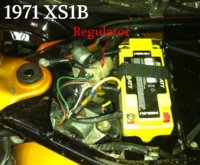
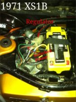
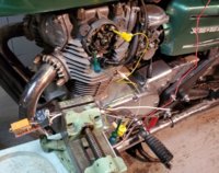
The easy way to do a charging system disabler is to either unplug the regulator, easily done on the XS1s since the regulator connector is accessible under the seat,
Angus67-71XS1B02.jpg

Or, add a disable toggle switch to the brown wire where it feeds into the regulator.
Angus67-71XS1B03.jpg 70-71_XS1-XS1B_ChargingCircuitColor_CutOut01.jpg

But, I wanted to be clever and add an automatic cutout, using a NC (normally closed) power relay.
70-71_XS1-XS1B_ChargingCircuitColor_CutOut02.jpg

When the relay is powered, the regulator becomes unpowered.
When the relay is relaxed, unpowered, then current flows to the regulator.
 
Last edited:
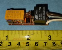
This is the gadget I was tinkering on.
20191130_Prototype01.jpg 20191208_Prototype05.jpg

This depicts its controller logic.
20191125_XS650-ChargeDelay-Logic - v01.jpg


When the ignition is switched on, the "Running?" logic circuit immediately powers Relay1.
This switches out the "Run Power" wiring, which cuts power to the regulator and rotor.
It also diverts power to "Relay2", which now connects the point/coil signals to the "Accumulator".
The brown wire power to the ignition system remains unchanged.

Now the alternator/regulator/rotor are disabled, cutout, and full battery voltage is available to the ignition system.

The "Accumulator" watches the ignition system during kickstart, and determines if the engine has indeed started.
When that happens, it signals the "Running?" logic that the engine is indeed running.
The "Running?" logic then unpowers "Relay1", and the gadget enters a passive state.
"Relay2 then switches off, disconnecting the ignition system from the "Accumulator".
"Relay1", now unpowered and relaxed, sends power downstream to the "Run Power" circuit,
which now powers the regulator, and charging can commence.

In this "Running", latched-out, relaxed state, this circuit draws only about 12 microamps, virtually no impact on the electrical system.
In case of a momentary run and stall, the ignition switch must be cycled off/on to re-enable the cutout device.
 
Last edited:
But, I ran into a couple of design flaws. The big one is the noisy power, caused by the ignition coils. The circuit is watching tiny signals, in a noisy environment. Kinda like trying to do brain surgery during a combo hurricane and earthquake.

So, this project is shelved for now, awaiting a suitable modification...
 
Back
Top