7 wire Chinese regulator Q

barncat

XS650 Addict
Messages
359
Reaction score
69
Points
28
Location
Candor NY
Doing another XS cafe build with a Hodaka tank. '73 modded motor kick only with stock stator/rotor and points.

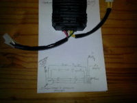
Found a wiring diagram on xs650chopper for a 7 wire reg/rec, but not sure if the white wire on this new Chinese unit is comparable to brown on others... if so this should be a direct swap, with the 3 nylon screw mod. Hope the handwriting in pic is legible.

Opinions?
 

Attachments

  • 20170627_134029.jpg
    20170627_134029.jpg
    116.8 KB · Views: 162
If you can find a part number, etc. on the thing, sometimes you can google the info and come up with a wiring diagram somewhere.
 
When you adapt the later '80-'84 ground switching type regulator to the early '70-'79 alternator, there's another step besides just ungrounding the inner brush with the 3 nylon screws. You then have to supply that brush with a source of switched power. The inner brush then gets constant power whenever the key is on and the outer brush has the ground switched on and off by the regulator. When the regulator turns the ground on, this completes the circuit and the alternator puts out a charge. When the ground is switched off, you get no charging.

The regulator portion of your combined unit also gets hooked to a switched power source in the harness. The regulator "reads" the voltage from this and when it falls too low, it turns the alternator on. So, you can't just hook that white wire to the black one from the alternator inner brush, you need to connect a switched power wire to them too. It could be 2 separate power wires from the harness or they could share the same one. Now, this is assuming the white is the wire that's supposed to go to switched power in the harness and the green is the regulator output (switched ground) and supposed to go to the outer brush.
 
No model # on part at all. Did Google that type of part but few results and nothing definitive.

Thanks for the thorough explanation 5T. Electrical engineering is not my strong suit. At this point I'd just be guessing as to internal design of the part. The only safe assumption is that red goes to battery. Black, white and green a crap shoot. I could always reuse the vintage reg and rec (have numerous ) or buy a vr115 but then I'd need to make a rectifier...
 
Barncat, you could try doin' the rectifier test on the 3 yellers, using the red and black as the power and ground outputs. If that works okay, then you've at least confirmed the red/black, and removed them from the puzzle. If, for example, the black doesn't work as the ground for the rectifier test, try another color, 'till you get it. The test won't hurt the rec/reg, the meter's test voltage/current is gentle...
 
Back
Top