74 TX650A Project – AKA “The Parts Bike”

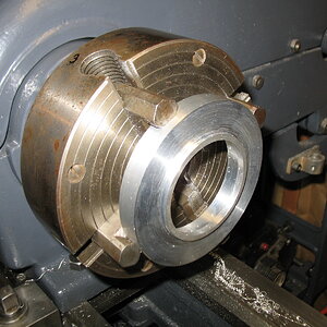
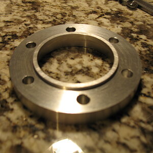
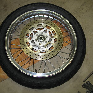
I made my own changer bar for my HF motorcycle tire changer. I couldn't see paying $100+ for one. I found a place that sold replacement plastic ends for their bar, so I just bought those (around $20) .....

http://www.wikco.biz/mc110.200.htm

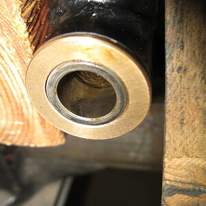
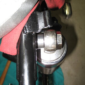
I studied all the pics I could find of the ready-made bars and made mine from a length of 1" square tubing. At first, the dismount end worked fine but the mounting end didn't work at all, lol. I couldn't find any good pics of that end so I just sorta winged it ..... and got it wrong, lol. When I finally did find a good pic of that end, it was obvious what I did wrong .....

Mount Bar End.jpg


I didn't angle the end of the square tube, holding it back from the end of the angle on one side. I made the whole end flush, and it just kept popping out .....

Bar Install End3.jpg


Bar Install End.jpg


So, I fixed it, lol .....

InstallEndFixed.jpg


..... and now it works fine. The bead of the tire sits on that little bit of angle exposed by angling the square tube back and holds the bar in .....

InstallEndFixed3.jpg
 
I never noticed that even the HF bar is angled until I had to heat form the HDPE for this mother of a tire. The HF one doesn't extend forward under the bead so sometimes the bead would pop under the end and I'd have to start all over again. Thank the tire gods it didn't do that for the final "this b**** is going on or I'm gonna burn it in the back yard" attempt.
 
Last edited:
Since I was such a dick to mike thought I'd try and redeem myself (a little).
the bar ends on the Coats 200 manual MC tire changer.
KIMG0805.JPGKIMG0804.JPG
That bar is about 42", weighs about 20 pounds and is basically indestructible.
the hook is perfect for that first levering of the bead over the rim when removing the tire.
I have one of those 3' mechanics pry bars, with the end rounded so it doesn't cut or gouge, to keep the tire from going back on or off while bringing the other bar around the rim. And yup still have a couple of regular irons to aid that last foot of getting the bead over the rim.
Getting this tire off should be a good spring warm up, it's dated 94, the front on this 81 is probably the original tire.
 
Different but somewhat related subject...I swore I wasn't going to change things on this bike. Just going to keep it stock and fix what's broke, that's what I told myself. BUT...while removing the front brake disk to do the tire change I just can't get past how HEAVY it feels. I weighed it and it weighs a whopping 6.43 lbs. When I decided to change the front disk on "Dad's bike" I bought a pair of FZR-600 disks 'cuz they were cheap on eBay, so the other disk is calling me from the corner of the basement..."I'm much lighter...much lighter..." which I try to ignore but it keeps persisting. So I weighed it and it weighs 3.62 lbs. giving a little over 2-3/4 lb. weight reduction. Soooo, I have given in and decided to make just this ONE tiny exception to my initial plan. Now I need to make another adapter before I can finish putting the front wheel back together. Guess I know what I'll be doing tomorrow after cleaning up from the tire change, time to twirl lathe handles again heh heh heh.(oh darn!)
 
I started the disk adapter yesterday and after taking all the measurements it works out that the Parts Bike adapter is about 0.070” thicker than the one for dad’s bike and the leftover bar from that was just barely thick enough to provide a workable pilot for this adapter. Sometimes you get lucky…

First step was cutting a piece of 5/8” x 4” wide aluminum bar (from McMaster) to start with a 4” square and drilled the center for a fixture hole so I could turn the O.D.. I then cut the corners off to reduce the amount of stock. I used the same fixture (a piece of scrap shaft with a tapped hole on-center) that I used for the adapter on dad’s bike.


With it centered in the 4-jaw I faced it so it was flat and parallel to the opposite side and bored it to fit the center hub and disk mount pilot of the wheel.


When the wheel side was done I checked the fit (which was good), flipped it around indicated it back on-center and cut the disk mounting surface and disk pilot.


I used a the FZR disk and a transfer punch to transfer the hole locations and drilled them on my bench-top (or in this case basement floor) drill press.


I recently learned the drill press was either sold in 1942 or 1943 as that’s the only years the “Mohawk” style Craftsman drill presses were built. After WW2 the style was changed. (little bit of Craftsman trivia)


Just to prove to myself that I “got all my sums right” I placed the disks on the countertop on the mounting surfaces and they are at least “Mk. 1 eyeball” close on centerlines.


The wheels are ready to go back on so it’s on to other assembly tasks, like pressing the bronze bushings in the swingarm so the swingarm will be ready to go back in.


And all that just to save a tick under 2-1/2 lbs. of un-sprung and rotating mass. Probably reduce 1/4 mile times by 0.03 seconds...at least...
 
I got some longer disk bolts today to accommodate the thickness of the disk spacer and with a wee drop of blue Loctite the front wheel is DONE and ready for install. It dawned on me while working with the disk that the swept area of the FZR disk is smaller than the TX disk so I will need to grind off about 5mm of the bottom of the brake pads to clear the edge of the cutouts in the disk.(added to the list...) I like the large piston area of the TX caliper for the additional brake force but the equally large diameter (48mm) brake pads don't fit disks made for newer style rectangular pads used in more modern bikes very well. Believe it or not, the TX caliper has about 34% more area than the blue spot caliper I used on Dad's Bike. (also weighs like 3x as much, or seems like it.)

Afterward I cleaned up the inside of the swingarm pivot tube with some sandpaper and put a thin smear of grease inside and pressed in the new bronze bushings.


I checked the fit of the pivot sleeve and...


...that's as far as they go so not so great. I tried another sleeve I had and got the same result. Checking the ID of both bushings and they were 22mm as they were supposed to be so either the bushing has a slight taper or the swingarm tube does. When I did the bushings on "Dad's Bike" everything slipped together and fit perfect, oh well. I ordered an adjustable 22mm hand reamer (should be here Monday) to remove the "bonus material" from the inside of the bushings.
 
Last edited:
Inquiring minds wanted to know and since I still have the left blue spot caliper I dug it out and weighed the two calipers. The blue spot weighs 983g (without mounting bolts since I don't have them) and the TX weighs 1613 grams with mounting bolts so it weighs about 60% more. I stand corrected.
 
I bought some Bonneville T100 shocks on Ebay to replace the rusty stockers..


...and needed to make some bushings to adapt the 14mm shock eye to the TX's 10mm lower shock mounting bolt. Sooo, time to twirl more handles...


...and turn a piece of Delrin into the required spacers.


When I get the swingarm bushings reamed and the swingarm back in I can see how much of the chain guard will need to be massaged to get the lower part of the shock to fit.
 
I took a look at the shock clearance to the chain guard this morning and there was a small interference. Since I had the shocks in my hand, I decided to move the bushings as far to the inside as I could to pick up a little clearance for free. Using two sockets and the vise I moved them about 1mm, just so the inner bushing was a little past the outboard side of the shock eye.


I knew there would still be interference so I used a die grinder and a carbide burr to lower the bottom edge of the chain guard sheet metal so it was even with the reinforcement inside the chain guard.


Now there should be decent clearance and if not I can always make a little more with the die grinder. I won't know that until I can install the swingarm and I can't do that until the reamer shows up.
 
While waiting for the reamer I thought I would clean up and assemble the brake caliper. After about a half a can of brake cleaner and a lot of compressed air I got the last of the gunk and grease. (from popping the VERY seized pistons out) A dental scraper was very helpful getting the grooves de-gunked and after a few passes with some coarse steel wool the grooves looked perfect.


The OE Yamaha seal kit came with rubber grease so I lubed the seals and installed them and then lubed the piston OD's and the pistons slipped in sweet as you please.


With the caliper bolts all torqued up the caliper is ready to be installed.


The brake pads still needed trimming to work with the FZR rotors so a little die grinder and hand file work and now there's plenty of clearance between the lower edge of the pad material and the disk cutouts and the pad backing plate and the disk buttons when the pads wear down to the nubbins.


I'll need to check the wear indicator tab too to make sure it won't hit the disk button with everything installed. Nothing a grinder can't take care of if it does.
 
The reamer showed up after lunch, Woo Hoo! It was $19 on Amazon and is typical Chinese quality, lots of burrs, gritty and the knives were difficult to move by pushing on with a finger but looked like it should work.


After looking up how to adjust them I adjusted it so it just kissed the tight spot at the very inner part of the bushing.


Three light passes later and the inner sleeve slips in like budda'! For $19 I was pleased with how it worked and hopefully I'll never need it again.

 
Last edited:
And the final (little) project for the day. I spent about two days on Dad's Bike straightening, breaking and replacing the hollow turn signal mounting studs and brackets. Not much I can do about the brackets but decided it would be nice if I could make my own hollow studs out of better material while still respecting my "cash conscious ethos". (Still really like that one Rasputin!) I started with some metric Gr. 8.8 threaded rod from McMaster which was about $4.50 for a 3-foot-long piece, enough to make about 18 hollow studs.

I decided not to try anything fancy for the first one, just chucked it up, center drilled it and drilled about half-way from one end. I then flipped it around, center drilled it and drilled it through. I can just see in the center where the holes meet there is a tiny step, but it doesn't hurt anything.


So I got that going for me, which is nice...
 
Last edited:
I made some good progress today. First task was to install the swingarm into the frame but before I did that, I wanted to pre-charge the bolt and sleeve with grease. I'm glad I did because the nut end had grease coming out the sleeve in two pumps. The other end was a different story, even after four pumps grease still wasn't coming out the sleeve. I poked a pick down in there and it was as hard as a rock, I couldn't get the pick in more than a half inch. I used a hand drill and 3/16" bit and it was still hard to drill. What came out was more like plastic and grit than grease...


...some of it was powdered! I have no idea what that was but I'm glad I checked because there was no way grease was ever going to get through there.

After I got the swing arm in, I put the shocks on and there was still a little interference toward the front of the cutout in the chain guard. A little bit of work with the die grinder and now there is 2mm clearance minimum.


I also needed to make some aluminum spacers to take up the extra space between the frame and upper shock eye.


I really wanted to get the beast off the motorcycle lift and on the center stand so the next tasks were to get the front and rear wheels in. There were a couple of little tasks that needed to be taken care of first, like cutting and fitting the fork gaiters (9 pleats seems to work well on the early forks without needing any clamps or zip ties), installing the brake stay, installing the inner fender, etc. But finally the wheels are in and it's back on the center stand and looking MUCH more like a motorcycle! I really like seeing the pile of parts get smaller and smaller.


With the front wheel installed I checked the disk centering and it's within about 0.010" of being perfectly centered in the caliper judging by the drill bit's I could get between the disk and caliper.
 
Last edited:
I check the grease flow before assembling things. This also flushes out all the old grease .....

GreaseCleanOut.jpg


Something else I do is add a couple additional holes at the center of the pivot tube. This allows grease to fill the center of the swingarm besides just lubing the bushings .....

PivotTubeModded2.jpg


PivotTubeModded3.jpg
 
Back
Top