'75 650B Charging System Guidance Needed

REPETE

XS650 Addict
Messages
180
Reaction score
239
Points
43
Location
Seminole County, Florida
Hello All
After nearly two years of trouble free smiling miles on the 650B many of you helped guide me through from a non running (23yrs.) bike to my favorite ride I now find myself in need of assistance again.
Please bare with me on this. I do try to be as self sufficient as possible before I ask, but my searches on the forum seem to torn up mostly information for 1980+ or bikes with PMA's and info. on removing the rotor - which I cannot determine is necessary or not.
Here's the background:
  • charging system suddenly stopped working
  • brushes are basically new... have maybe 1500 mile on them. I removed & examined for obvious damage or wear - there was none and they were reinstalled.
  • quick test indicates that about 9-10.5 amp output that would increase to high 11's above 4k rpm
  • rather than play around with 46yr old rectifier and voltage regulator I bought a solid state combination unit - an ES350 something or other that I found recommended here on the forum.
  • hooked it up and no improvement
  • ran tests on wiring from stator to old rectifier per instructions in Clymer Manual.
THIS IS WHERE I START TO GET LOST - UNDERSTANDING THE DATA I'VE COLLECTED AND WHERE IT'S LEADING ME.

  • identified the 3 white wires from the stator as #'s 1, 2 & 3 and then tested them in combinations with each other. results were: 1 to 2 = .7 ohm 1 to 3 = OL 2 to 3 = OL I believe this indicates a short / grounding situation in wire #2.
  • next test directed testing each white wire with one test lead on the wire's end and the other on the stator housing. results were: #1 = .282 ohm #2 = .281 ohm #3 = OL instructions read that if any of the readings is anything other than OL (infinity) the stator is bad.
Based on the this my stator has gone bad. Or, did I miss something that would prove otherwise?

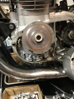
Working on the belief that my stator is bad, I began removing it last night. It was late and I stopped at that pesky little bolt tucked away where I circled in the picture. I didn't see that right away and was tugging away on the plate that protects the harness :oops:
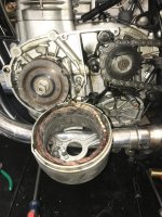
But, the stator is apart and I'm not sure what my next steps should be.

  • does the rotor come into play here at all? i.e. should I be planning on removing it for purposes of rebuilding or replacing the stator?
  • what am I looking for in the stator other than an obvious broken copper wire?
  • are there anymore tests I should perform once it's removed or start looking into having it rebuilt or replaced?
  • are either the stator or the rotor supposed to be magnetized? I thought they would be, but they aren't.
This is about as far as I can go with this without some experienced guidance, so please let me know if what I've indicated seems correct and if I'm on the right path and where I go next.

Thank you!

Charging System 20210902-011.jpg
 

Attachments

  • Charging System 20210902-02.jpg
    Charging System 20210902-02.jpg
    253.1 KB · Views: 159
The first thing I would do is to measure the slip ring resistance on the rotor brushes out ---rotor still on the bike
Then since you have the stator out I would check it according to service manual instructions found there
or elsewhere

https://thexscafedotcom.wordpress.com/2011/01/10/xs650-manuals/

Please check that the Regulator / Rectifier combo is for a pre 1980 bike

My first guess is Rotor but I have had stator failure also.
 
I suppose it's possible your stator has gone bad but they hold up pretty well. I'd test it again now that it's off. I recently tested several looking for a good one to sell to a guy. They were all off the bike and while my readings between the white wires didn't match up to the book values, they were all the same on all three stators. I think I was reading like 10 to 12 ohms between the whites. I figured they all couldn't be bad and it worked out OK, that guy's bike is charging fine again. So, give yours another test now that it's off.

Your inner slip ring looks very, very dirty, maybe to the point that the brush couldn't make good contact anymore. I'd clean the slip rings then test your rotor. I just use a little chrome cleaner on a rag to polish the rings clean and shiny again .....

jrGGd3G.jpg
 
  • identified the 3 white wires from the stator as #'s 1, 2 & 3 and then tested them in combinations with each other. results were: 1 to 2 = .7 ohm 1 to 3 = OL 2 to 3 = OL I believe this indicates a short / grounding situation in wire #2.
  • next test directed testing each white wire with one test lead on the wire's end and the other on the stator housing. results were: #1 = .282 ohm #2 = .281 ohm #3 = OL instructions read that if any of the readings is anything other than OL (infinity) the stator is bad.
Based on the this my stator has gone bad. Or, did I miss something that would prove otherwise?
Yes, all 3 leads should show about a half an Ω to each other in any combination of the 3. All 3 wires to ground should show OL (open). You might get lucky and find the break (open wire) but I doubt it. If your readings are correct, it's time for a replacement stator.
 
Just noticed your second pic....
Like 5twins says, that inner ring is way to dirty. On the other hand, the outer ring looks way too clean for one that's been working. I'd suspect the spring tension is pretty much gone on that outer brush.
 
Jan P / 5T I appreciate the reply.

I definitely purchased ES350 for pre 1980 bike. It was basically a plug 'n play excepting that they had the wires (3 white, black & red) reversed from where they needed to be inside the connector. Was an easy fix.
I had no idea that a rotor could go bad. The book does instruct to test the rotor... but the picture is so bad and they show it being tested with the stator in place and I had no idea what they were talking about until I saw this picture posted by 5T. Now I clearly know what a "Slip Ring" is! :)

I will also check the brush installation, but as I said.... they're basically new. But I do see what you're talking about Jim.

I'll work through this again tonight and report back with any findings. This was helpful. Thank you
 
THANK YOU JIM!!!
I just glanced at the info. and I'm less concerned now.
I'm about to leave the office for the day but won't be home till early evening at which point I'll sit down with a nice cold beverage and read that information thoroughly.
I'll update as soon as possible.
You guys are all so helpful.
 
I get a little bad vibes of the plug and play Reg / Rec combo where pins needs to be shifted

I definitely purchased ES350 for pre 1980 bike. It was basically a plug 'n play excepting that they had the wires (3 white, black & red) reversed from where they needed to be inside the connector. Was an easy fix.

I am not saying it is wrong at this point in time ..But if you like -- please post which one you have there
Better safe than sorry.
I know that some regulators fry faster than one can spell " Blue Smoke "
if connected with wrong polarity.
And then cause other problems worst case scenario.down stream Expensive Problems.
$ 100 a pop...
 
A few years ago I had the same issue as you. Charging system started to fail for no apparent reason. Turned out to be the rotor. An easy fix and @Jim offers a very reasonably priced service. I also wired in a digital volt meter mounted to my handlebars so I can see what the charging system is doing. It will also let me know if/when the charging system begins to fail again.
img_6337-jpg.100761
 
Good Morning
I got a bit done last night, but haven't completed everything I wanted to accomplish.
First up, lets take a look at the replacement regulator/rectifier as well as the wiring connections on which I had to reverse the plastic bodied connector. I did the best I could with the photos and I think they'll demonstrate that all wires are properly aligned.

Here's the replacement unit....
IMG_9192.jpg


I know I'm eating up space here but to be thorough and leave no stone upturned here are pics of the wiring connections....

IMG_9193.jpg IMG_9194.jpg IMG_9195.jpg IMG_9196.jpg IMG_9197.jpg

Unless I'm fooling myself, the regulator is the correct one and is wired correctly. But it certainly didn't hurt to go back with fresh eyes and review.

The brushes are still in place in the sator so I'm able to see the backside where they contact the Slip Rings. They are evenly worn - nice and flat - and to the push of a finger have equal spring resistance.

Regarding the different looking "dirty" Slip Rings on the rotor - neither were dirty! The difference in coloration appears to be from differing metals maybe? But they are clean.
Then came the rotor test that I didn't grasp following the poor (to me) illustration in the Clymer manual.

Take a look....

IMG_9191.jpg


If I'm reading the this correctly, the rotor is shot and has to come off.
Is the securing nut that holds it left hand thread?

Jim, once it's off later today I'll sit down with that cold drink I promised myself and finally read through the info. you sent.

As was suggested, I'll also go back and retest the stator as per the instructions in the manual and see if I come up with different results. I'd be very surprised if both parts went bad at the same time. And as was said earlier... the stators rarely go bad.

More to come later. Coffee cup empty... time to get to work.

Onward
 
Do you have the correct puller for the rotor?
 
If you don't use the correct puller, there's a better than even chance you'll bend it past the point of being usable.
 
Good Morning
The link posted by Jim explaining the charging system and which incorporates a thorough troubleshooting guide authored by gggGary is excellent!!!
I'm glad I was directed to it... and also Jim's services for rebuilding the rotor.
I did go back and retest the stator and everything is as it should be. What I believe I did wrong in the first place was that I took readings at the incorrect connector. I used the one that unplugged from the rectifier not realizing that it was "downstream" from the terminus connector of the stator harness.
Rotor is now on its way for rebuilding.

In the interim I need to locate a replacement grommet for the stator harness. It was dried and cracked into pieces. I'm referring to the square-ish one that slides into the crankcase and seals against the backside of the cover. I cannot find a part number on any of the part schematics I've been looking at nor can I locate any by searching with just various descriptions.
Is there a known source or these?

Unrelated, but noticed while tracing out the stator wire is that I have a split rubber air cleaner joint rubber. A search for a replacement (even having the part #) has been unsuccessful.
Is there a known source for a replacement?
 
Last edited:
Thank you Skull!
I only need the rubber joint. I had looked on MikesXS website previously and unsuccessfully. I'll dig a little deeper or call this time.
While the stator is out I want to replace the hardened harness sleeve and the grommet I had mentioned earlier.
If anyone knows where those can be gotten I'd sure appreciate being pointed to it.
 
Back
Top