'82 SJ Simplified wiring question

nighthog

A bit of a bike hacker
Top Contributor
Messages
423
Reaction score
1,614
Points
143
Location
Chippenham, Wiltshire, UK
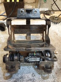
Hi all, I'm preparing to rewire my '82 SJ that has had all the extraneous relays removed, an earlier-type RH handlebar switchblock with lightswitch fitted and LED indicators. I'll retain the starter safety relay. I've amended an eBay battery box to relocate the flasher relay, safety relay, fuses and starter relay - here's the rough fit:
20211221_101106.jpg

I've spent a lot of time going over the info here, especially the stuff from the tech section, but I still get a bit unsure when what I see on the diagrams doesn't match what I see on the bike, so time for a sanity check to make sure I've understood things correctly. Main concern is the white/black on the igniter - I think this is to the removed sidestand relay and I can just leave it.
This is built in Inkscape, I'll be happy to share once it's complete and verified.

XS650.png

Inspired by Jayel's stuff, of course. I find it so much easier to follow when the colours are in front of me. Anyway, correct so far?
Thanks -
Cliff
 
As it stands drawn Cliff, you have ignition power coming out of the fuse, splitting and going separate ways to the kill switch and starter safety relay. That will work mind you... but it sets up a scenario where you could have the ignition off via the kill switch... and still be able to drain the battery with the starter. As long as you're aware of that it's OK, but I'd suggest going thru the kill switch first and splitting out after. That way the kill switch will also kill the starter solenoid.
 
Yes, the black/white should be the sidestand ground. Should work as you've drawn it.
 
Thanks, Jim. Yes, I'm aware and in practice the only time I use the kill switch is to stop the motor so I can find neutral when in sticky traffic, then it's back on again!
My worry was the white/black or black/white connection. White/black seems to be the one to the sidestand ground - agree?
 
White/black seems to be the one to the sidestand ground - agree?
Yes... agree.
I have a few spare boxes. One's an '82 box I changed from the 8 pin to a 6 pin connector. The white/black is the wire I cut and stowed. I tested it on my bike to make sure it's works correctly... it does.


PXL_20211229_224556434.jpg
 
Thanks, Jim. That confirms what I thought.

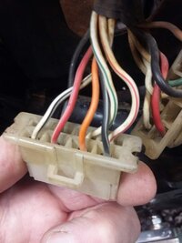
Gary - the wires from the pickup are black, orange, grey and turn into black/white, white/green, white/red (not necessarily in that order!) at the connector. What's marked B/W on your pic is, I think, the W/B I see. There is a B/W but that's the one from the pickup. Hence the confusion ....

Do you reckon the Yamaha electrical dudes had a sense of humour?
 
the wire to ignore is the one by itself on one end of the connector, in 82 they went from the previous 6 wire connector to the 8 wire and used just one more wire. You can do a bit of plastic surgery and plug n play 6 to 8 wire TCI to harness, either way.
pickup wires.JPG
 
Vintage connections sells connectors for dirt cheap. Damn good quality too. Not sure what shipping over the pond would be though. Since you're making a new harness, go ahead and replace the 8 pin with a 6 pin. Here's the '82 box I switched over. White/black is cut and tucked in at the box.


zzx.jpg
 
Well, probably not best to do this after a couple of New Year drinks, but here's the completed diagram. I decided to go with Jim's suggestion re the kill switch - no harm in belt-and-braces. As ever, feedback welcome - if it looks good to you guys then I'll see if I can upload the svg file for others to play with.

XS650.png


Now I need to get the modified battery box powder coated and work up a shopping list of electrical bits. We don't seem to have Vintage Connections over here (well, we do have a version, but it's for car stuff) but we do have https://www.vehiclewiringproducts.co.uk and https://www.bikerstoolbox.co.uk. I've also used https://www.autoelectricsupplies.co.uk over the last few years and they are great, but I don't think they have the connectors I'm looking for this time around. If I can avoid chopping the ends off stuff just to fit similar but not quite the same connectors, I will!
 
As ever, feedback welcome
Everything looks good... at least nothing jumps out at me.
Another suggestion though. You only have one ground drawn for all lights, alternator, and ignition. That would work, but it's a lot to ask of one gnd. I subscribe to old school ways.... no such thing as too many grounds.
 
Here we go. The .svg file is just a bunch of XML, so I renamed it as .txt. Anyone interested can copy the file and rename it back to .svg. I hope it proves useful to somebody.
 

Attachments

  • XS650.txt
    346.2 KB · Views: 124
A simple disable switch would be to ground this wire.
Here's a schematic a member drew. I don't know how accurate it is. FWIW, what happens is with that wire grounded, the transistor in the upper right that goes to the coil won't turn on. Could be added to an igniter box without it.
ignition_schematic.jpg
 
Back
Top