Yah. I saw the thread about Pamco Pete. I bought my kit through XS Direct. Just had it delivered.
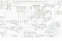
I am posting my schematic for the TCI board. I don't know if I will spend anymore time on it, as I have the pamco kit here now. I may try the TCI board with the new coil, just out of curiousity. But I think the IC on my TCI board is shot.
As far as the schematic goes, I think it is reasonably accurate. The arrangement of components around the inputs and output make sense and I was able to check them. The arrangement of components around the IC is a little more sketchy. Since I have no info on the IC, can't really look at that part of the schematic and say for certain it is correct. The zeners on this board are 8.2 volts for ZD1 and 6 volts for ZD2 and ZD3. R1, R2, ZD1 and C1 make up a small on-board voltage regulator circuit for the igniter. It basically provides a stable 8.2 volt supply voltage for most of the board, rather than relying directly on a fluctuating battery voltage. The output transistors T4 and PTR use a non-regulated voltage via the R./W wire. The board appears to have four fuses on it. Well, they are labelled as resistors, but the resistance is less than 1 ohm and they are encased is a white package. My guess, given the schematic layout, is they are fuses. The IC on my TCI board is labelled as EWD101. Given that it is a Hitachi igniter module made using Hitachi components, this is likely a custom made chip from Hitachi. Good luck finding a replacement for that. I checked all the electrolytic capacitors, transistors and diodes. All were good. The only definitive fault I found was some dodgy soldering around R1 and R2 as well as some suspect soldering where the wires attach to the board. Everything was resoldered.
I started my repair using a troubleshooting guide from 650central called: If your XS650 with standard Yamaha electronic ignition has no spark. This was a very good guide except for at step 6 they suggest disconnecting the pickup coils to test them. This is crazy talk. The pickup coil impedances as well as the primary coil impedances can easily be checked from the ignitor connector. This way, you are also checking the wiring going to these components as well as the components themselves. Also the colour coding that he lists for the pickup coil impedances for the 83 is wrong. Follow the colour coding for the 80 81 models.
If anyone has any questions, ask away. Maybe this diagram will help someone else.
Ken