Contamination or Oil on Alternator Brushes

Paul Sutton

I Collect Fingers
Top Contributor
Messages
2,728
Reaction score
7,207
Points
513
Location
Cardiff UK
I have made several comments regarding low voltage from my alternator in the following thread (See mainly Page 2 of thread):

http://www.xs650.com/threads/well-that-didnt-last-long.52169/page-3#post-550808

The situation is that the voltage output from my alternator is low and the observation is a weak rotor magnetic field. I have spent considerable time trying to resolve the problem and have determined that my SH is electrically sound. The issue is poor conduction through the brushes and rotor even though the rotor is perfectly functional as with all the electrical wiring, connectors and the Rec/Reg (See the link above for details).

When I measured the resistance of the brushes and rotor assembled combined I observed 14 Ohms. I know that each brush contributes approximately 0.1 Ohm and the rotor is 5.3 Ohm. Therefore something else is offering a resistance and this has to be the copper/brush contact.

I have sanded the copper rings lightly as well as the ends of the brushes. On reassembly the combined resistance returned to essentially that of the rotor plus brushes. I started the engine up and all is good with the regulator controlling at its preset of 14.2V. I headed off on a 20 mile ride and all was well for the first 10 miles and then the voltage started to drop to a low level as in the past.

What is contaminating the brush/copper contact point?

The only explanation I can think off is oil vapors are leaking from the crank seal. I cannot see any obvious sign of oil leaking and the oil seal was replaced a couple of months back when I fitted the new rewound rotor.

Has anyone had a similar experience like this??

Thank you for any thoughts and suggestions, but bear in mind that all the electrical testing has passed.
 
Forgot to mention that the resistance is again high across the brushes and rotor following today's ride.
 
Just measured the resistance after the above trip:
  • 64 Ohms
  • Cleaned outer copper ring with petrol and it dropped to 46 Ohms
  • Cleaned inner copper ring with petrol and it dropped to 24 Ohms
  • Lightly sand both rings and back to 8 Ohms which is normal for a hot rotor
Note: All measurements were done with the brushes in place.
 
Last edited:
Could be there's a bad place in the rotor that's getting hot so the resistance increases. Sometimes you need to measure things like this many times under different circumstances to be sure you aren't fooling yourself and jump to a bad comclusion. Re; brushes and rings, where there's friction there's electrical conductivity. I really would not suspect the brushes or rings in your case.
 
Last edited:
I have measured the resistances some 2 hours after the ride. The resistance still shows the next day when the bike is cold i.e. it is real and reproducible. The cleaning with a very light sanding of 400Grit is reproducible to restore the resistance and voltage output. 600Grit was no good at cleaning. The inner ring shows the greatest decrease in resistance on cleaning and it is probably the one exposed to the highest temperature due to conduction from the shaft.

Taking xjwmx's point about temperature the inner ring probably get the hottest. I read once upon a time that with cars you must avoid getting oil on the rings and brushes because they will react to give poor conduction and a useless alternator. So perhaps oil vapors are reacting on the inner ring faster???
 
Could be carbon dust buildup in the sanding scratches. 400 is a lot rougher than I do. You can start with that but I usually finish up around 800-1000 for a nice polished finish.
 
When I installed the rewound rotor the scratches from the supplier where quite coarse so I polished the rings. This problem occurred while the rings were polished. The issue is that I observe a resistance build-up at the brush/copper contacts. When the contact is cleaned the resistance drops and the rotor then produces a strong field and the alternator output returns to normal. What is screwing up the brush/copper contact??

I have ordered new brushes and an oil seal. I will thoroughly clean the alternator area, polish the rings then strip of any waxes with solvent and then fit new brushes. I realize the obvious culprit is the rotor but this all checks out 100% as does the Rec/Reg unit. Checking the internet does bring up several mentions of oil damaging the conduction layer in alternators but I just do not see much oil at all.

I shall labor on.
 
Last edited:
Anytime you measure resistance touch the probes together first to insure it goes to (close to) zero.

Do this. When you think it should read high, measure from the brush screws directly to the slip rings. Push the probes in hard. Remove the lug from the screw first in case there's something wrong with your wiring. Do the same when you think it should read low. You'll see they read the same.
 
I have no other rotor to try.
I have tested my meter against 1% tolerance resistors and it is fine - Just checked and 100 Ohm reads as 99.7 Ohm
I always check my meters zero which is 0.7 Ohm with probes touched together.
I have done the testing both with and without wiring connected.
At 20 Celsius my rotor gives 5.3 Ohm when measured from ring to ring.

I am not convinced the issue is oil as I have a new seal in place but will replace this Wednesday. When engine is hot I do notice a strong smell of epoxy hardener when I take the alternator cover off so may get a chance to clean an polish everything today and ride with the cover off. Will also do current measurements both cleaned and not cleaned as it is currently showing 14 Ohms.

Two days ago with 16 Ohms showing the magnetic field was weak. This did not improve when I jumpered the brush connections directly to the battery terminals. Once the rings were cleaned the field strength was very good. Will repeat this and take current measurements.

If someone told me they had this issue which I am observing I would not believe them - But very strange and reproducible. Must be a Gremilin

Thank you everyone for your suggestions.
 
We discuss brushes, current density, and slipring patina in this thread:

http://www.xs650.com/threads/dead-rotor-best-options-to-fix-replace.36211/

Another one to review:

http://www.xs650.com/threads/alternator-brush-question.1110/

Friend of mine had an automotive charging problem, traced down to an inconsistent alternator rotor. When you would *tap* the rotor, its resistance would change, intermittant internal opens and shorts.

Edit: Forgot the point to this. Sometimes, when manipulating things, you get a change, which leads you down the wrong path. One member here heard of attaching the brush copper wire to the inner hole of the brush with superglue. Sounds goofy to me, he claimed it works. I can imagine intermittants from the wire/brush connection. I wonder if some aftermarket supplier is doing goofy things like that. Could try continuity tests of the brush terminals to brush face, accompanied with some wire wiggling, searching for intermittants.

Another thought is bogus brush material, spewing grunge on the slipring.

I guess you could check, and/or reflow the solder joints of the windings to slipring disc...
 
Last edited:
Brief update:

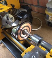
I have cut a taper on a bar of aluminium so I can mount the rotor in my lathe.
Rotor.jpg
I have sanded the rings on the lathe using 400 Grit followed by 600Grit.
I have checked the run-out on the rings and the maximum deviation is 0.002" which seems reasonable based on my research.
Using my new meter I have measured 5.3 Ohms as with my old meter. I have subjected the rings to considerable rocking and pushing with the meter connected and observe no deviations from 5.3 Ohm.
I checked the oil seal and there is no indication of any oil passing whatsoever.
I have retested the brown and green wires to the brushes and find no poor connections.

Question: Where on a special does the black harness wire tie into the frame? The stock Rec/Reg does not have a connection to the chassis from the black wire via the heat sink.

Unfortunately the mail service has delivered my new brushes, but no one knows where they were delivered to. Another hold up!!!!!! I need the new brushes to make current measurements.

It is my hope that my problems are brush related????
 
As soon as the rotor starts to rotate, some of the carbon on the brushes deposits onto the rings. If the brushes are too short, there is not enough pressure to overcome the buildup of the resistance caused by the accumulation of carbon on the slip rings so a high resistance will develop soon after you have cleaned the slip rings. The answer is to install new brushes even if the ones you have measure in range.

This condition is exacerbated if the run-out on the slip rings is anything but perfect because the "hill and dale" high and low spots causes an excessive accumulation in the low points. I went through this some years ago with a new rotor that only lasted a few miles before the battery voltage decreased due to the effect of the accumulated carbon in the low spots of the slip rings.
Here is a video of that rotor. Look at the lower part of the image to see the run out next to the tool. A good rotor will show hardly any run out, or at least the run out is not noticeable with the Mark I eye ball.


Here is a rotor that does not have any discernible run out. This is a rewound rotor from:
Custom Rewind
2014 Pratt Highway
Birmingham, AL
35214


Last edited:
I have 0.002" runout, should I attempt skimming this down on the lathe?
You could try new brushes first. It's difficult to cut the excessive run out on a lathe as the end result may not be smooth enough resuting in another type of problem, excessive wear on the brushes. The metal of the slip rings is a special alloy just for slip rings to provide good contact with the brushes but not result in excessive wear.
Another "trick" is to finish the cleaning process with an eraser on the end of a pencil. I do this with the engine running and the brushes removed.
 
Last edited:
Back
Top