Jonaven
XS650 Enthusiast
I'll go hive it a check ,when I was looking g I didn't see a Crack, the flash was pretty harsh in the surroundings
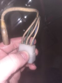
A bit confused eith the alternator wiring as it has these colorsVin # confirms its a Canadian 78SE.
Carbs need some identifying/. The connecting plate is not the same as whats used on XS650 BS38 Carbs.
Why is it different, has the plate been changed or are the carbs from something different i don't know. Maybe someone else will be able to identify and solve the mystery.
Your carbs don't have a throttle/idle adjustment screw on the left carb below the chock/enrich lever. Yours has a feed tube on the choke/enrich side facing the manifold and the black tops look factory??
This makes the jetting an unknown Before any advise taken in that area you need to see what is installed in these carbs and advise used on XS650 factory carbs may not be suitable for your carbs
@5twins will probably be able to identify.
XS650 78/79 BS38 Carbs
View attachment 208131View attachment 208132View attachment 208133
Definitely a points, (type B charging system), stator. That Reg/Rect should be right for your bike.
Post #2 has the diagram to wire in your combined SS Reg/Rect.
NOTE; The change of wire colours from the Reg/Rect to factory harness colours. and separate the wires to the 2 Connectors coming off the Factory harness
https://www.xs650.com/threads/wiring-in-a-70-79-combined-reg-rect-to-a-points-model-xs650.52339/
6 pin connector
3 yellow to 3 white.........any yellow wire to any white wire
Red to red
Green to black
3 Pin connector
Orange to green
Blue to brown
The white wires are all from the stator. The order doesn't matter.A bit confused eith the alternator wiring as it has these colors
Are saying the wires don’t have to be connected to the proper colours? Cause the diagram shows it needs to be, its the other 3 colours that don’t ,match upThe white wires are all from the stator. The order doesn't matter.
No. I'm not saying that. Someone will chime in. I don't have the diagram right now.Are saying the wires don’t have to be connected to the proper colours? Cause the diagram shows it needs to be, its the other 3 colours that don’t ,match up
Are saying the wires don’t have to be connected to the proper colours? Cause the diagram shows it needs to be, its the other 3 colours that don’t ,match up
Just so I'm clear, are you asking how to install the shift lever?does anyone have insight on how to attach the shifter lever
Essentially, I just looks a bit empty in there and wanted to make sure nothing else was missing , cause I have the lever and a bag of boltsJust so I'm clear, are you asking how to install the shift lever?
Looks like you have the original seals in there (red seal on clutch rod is a giveaway). One of our more educated gurus spotted the same on my bike. It promptly pooped its oil out after the first ride following long storage.Also question have some shofter assembly stuff in a box what is missing on there either than the lever
Altough i totally agree with your assumption, i think as a total greenhorn he needs to get these other things right first. The pushrod seals are hard enough to get right the first time for experianced shede tree mechanics. Some one learning about shift shafts are going to be in over their heads.Looks like you have the original seals in there (red seal on clutch rod is a giveaway). One of our more educated gurus spotted the same on my bike. It promptly pooped its oil out after the first ride following long storage.
My advise is to replace them ASAP.
A bit confused eith the alternator wiring as it has these colors