Flasher dilemma

Superdriver

XS650 Addict
Messages
120
Reaction score
62
Points
28
Location
Comox B.C. Canada
Hello. I have a 1978 XS 650 special. When I activate the turn signals either left or right, all turn signals flash at the same time. Its great to have 4 way flashers but this cant be right. If anyone can help me with this problem I would greatly appreciate it. Thanks. Bill
 
I would check the flasher relay
If you have a Voltmeter check what comes out off the pins ( or some sort of test lamp )
And that the wires are connected right
 
thanks. I have a meter and will check the relay and the connections. It is sort of fun having 4 ways but the problem needs to be solved. Take care. Bill
 
I would check the flasher relay
If you have a Voltmeter check what comes out off the pins ( or some sort of test lamp )
And that the wires are connected right
I just got a new voltmeter and I have to learn how to use it. I guess it would just be a matter of touching the ground with one probe and touching the pins until I get a current reading. Thanks again. Bill
 
I just got a new voltmeter and I have to learn how to use it. I guess it would just be a matter of touching the ground with one probe and touching the pins until I get a current reading. Thanks again. Bill
You need to have it on the Volt setting. . DC
If you connect power ( Ampere / Current ) to ground it will short circuit flash and smoke.
You can test it across the battery terminals Volt setting DC the black to ground - and red to +
And read around + 12 V
Then move the black to the cylinder head getting about the same
 
The turn signal circuit begins at the fuse on the brown wire to the flasher, then continues from flasher to switch on brown/white stripe - all that is common power to R & L. At the bar switch it splits on dark green (R) and chocolate brown (L), the dash indicator bulbs are powered in parallel off those wires. So, something is miswired allowing power to bleed across the dark green/chocolate brown part of the circuit - likely @ switch or dash.
 
You need to have it on the Volt setting. . DC
If you connect power ( Ampere / Current ) to ground it will short circuit flash and smoke.
You can test it across the battery terminals Volt setting DC the black to ground - and red to +
And read around + 12 V
Then move the black to the cylinder head getting about the same
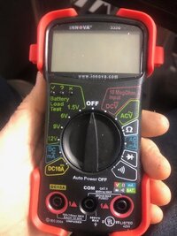
thank you very much. you have saved ne a lot of grief. my Innova multimeter has a battery test setting, a d/c ma setting, a d/c10a setting and a dcv 10meg ohm setting. which do you suggest I use. Thanks. Bill
 
The turn signal circuit begins at the fuse on the brown wire to the flasher, then continues from flasher to switch on brown/white stripe - all that is common power to R & L. At the bar switch it splits on dark green (R) and chocolate brown (L), the dash indicator bulbs are powered in parallel off those wires. So, something is miswired allowing power to bleed across the dark green/chocolate brown part of the circuit - likely @ switch or dash.
thank you very much. I will track the wires from the fuse and look for irregularities in the wiring.my most recent find today was that when I activated the switch left or right, the 10 amp fuse on the brown wire immediately blew. I took apart the switch and checked the wiring and cleaned the copper colored contacts. I could not see all of the wiring going into the harness as a couple of the screws were rusted into place. The wiringI could see was properly soldered. On reassembly, activation of the switch no longer blew the fuse but the signals still did not work. The adventure continues.
 
If normal tracing doesn't find an issue, you could unplug the bar switch connections inside the headlight shell and bypass the switch by jumpering brown/white from main harness to dark green from harness (and/or signal directly), then chocolate alternately. If that gets normal signal operation, it's the switch.
 
Yes it is good to ask before
I am not sure what meter you have If the wrong please give the correct name.

One Innova type there

1670577416818.png


At 12 o clock


1670577553858.png


The one with a wave above is alternating Voltage ..Try the one to the left of that on a flash light battery.
And if OK use on the Motorcycle
 
Does your motorcycle have self-cancelling turn signals? There is more than just a relay involved if it does.
Correct, but the canceller and reed switch are ahead of the flasher and common to both right and left signal and feed the flasher on yellow/ green stripe (from brown). So can't imagine they are involved in this issue as described
 
Yes it is good to ask before
I am not sure what meter you have If the wrong please give the correct name.

One Innova type there

View attachment 231644


At 12 o clock


View attachment 231645


The one with a wave above is alternating Voltage ..Try the one to the left of that on a flash light battery.
And if OK use on the Motorcycle
Hi. I have the Innova 3320 model
If normal tracing doesn't find an issue, you could unplug the bar switch connections inside the headlight shell and bypass the switch by jumpering brown/white from main harness to dark green from harness (and/or signal directly), then chocolate alternately. If that gets normal signal operation, it's the switch.
thank you. Take care. Bill
 
Yes it is good to ask before
I am not sure what meter you have If the wrong please give the correct name.

One Innova type there

View attachment 231644


At 12 o clock


View attachment 231645


The one with a wave above is alternating Voltage ..Try the one to the left of that on a flash light battery.
And if OK use on the Motorcycle
Hello. I have the Innova 3320 model (see Picture). I believe from what your saying that it would be the setting on the right in Red DCV or the Yellow one on the left DC10A Please let me know which is correct . Thanks. Bill
 

Attachments

  • innova 2.jpg
    innova 2.jpg
    87.7 KB · Views: 49
If normal tracing doesn't find an issue, you could unplug the bar switch connections inside the headlight shell and bypass the switch by jumpering brown/white from main harness to dark green from harness (and/or signal directly), then chocolate alternately. If that gets normal signal operation, it's the switch.
thank you. take care. Bill
 
Did this happen on it's own or after you did some work on the bike? Like maybe installing led bulbs in the turn signals?
 
Yes use the
Hello. I have the Innova 3320 model (see Picture). I believe from what your saying that it would be the setting on the right in Red DCV or the Yellow one on the left DC10A Please let me know which is correct . Thanks. Bill
Yes use the DC V --Volt
I don't measure current on a Motorcycle
It looks at the bottom of the meter -- that the left most connecting hole is used for that.
and 10 A can be low perhaps --- my Main fuse is 20 A on a 1980.
And as mentioned above the Current measurement is done by opening the circuit and have the meter in series
If get it wrong there is fireworks and smoke
Whereas Voltage is parallel
It is less risky measure Voltage

Perhaps that is a help please google if uncertain
https://www.dewetron.com/2022/07/how-to-measure-current-and-voltage/

But put it on DC V and test it on a Flashlight battery you'll get it right
 
Back
Top