
LTGTR
XS650 Addict
FITTING A TRI-SPARK TO YAMAHA XS650
I recently fitted a Tri-spark electronic ignition to my Yamaha XS650D.
I purchased the unit from Steve at Tri-Spark who lives in the same city as me.
Disclaimer – I paid full retail price for it and advised Steve at Tri-Spark that I will do a “install and review” for the 650 Forum”.
Cost 450 A$.
I consulted Steve on a couple of points - wherever that is the case I will lead with the words "consulted Steve".
Apology - my 77D is a barn find - it is a work in progress - since the photos I have rewired the bike.
The text for each photo appears under the photo.
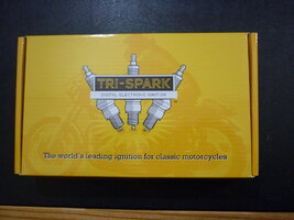
First Impression - nice packaging
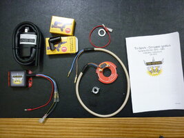
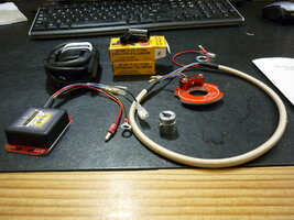
The above 2 photos shows there’s not much too it.
It seems to be the minimum number of parts to make an electronic ignition.
They have kept it simple and uncomplicated.
At this stage I notice how well built/designed/engineered it is.
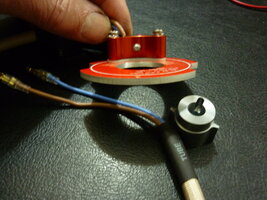
This is the base plate and the rotor trigger
The Base plate is around 3mm thick (strong) and fits where the points base plate used to.
The Rotor Trigger is nicely machined.
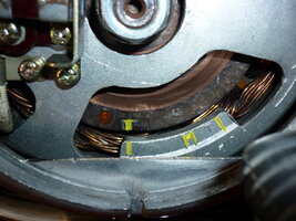
Set the timing marks on the rotor with the full advance mark on the stator.
This is very important.
This step confuses some people – look at it like this – you are simply telling the control unit that this is the maximum advance that it is allowed to achieve – the control unit will then deny this advance at idle RPM but allow that previously set maximum at around approx. 3000 RPM.
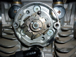
Remove the advance weights and springs.
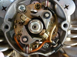
Take off the points plate complete with points (2 screws) and remove the nut, on the end of the shaft and remove the breaker cam.
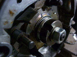
Pull out the rod, from the right side, that goes through the middle of the camshaft, and put the spring washer under the disc, that activated the weights, and push the rod back in.
Note – the disc will still be engaged with the original little pin that sticks out of the rod.
This photo shows the spring washer under the disc.
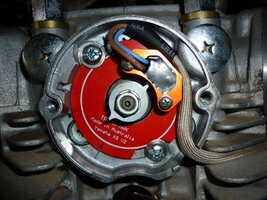
Fit the Tri-Spark base plate into the same recess where the points plate was and fit the 2 screws.
The 2 screws should be approx. in the middle of the adjustment slots in the base plate. Just nip the screws at this stage. (notice the screws aren’t in the middle of the base plate – by the time I took the photo I had timed my motor by turning the base plate – more of this later)
Fit the trigger rotor onto the shaft and secure with the original washer and nut – don’t fully tighten yet.
Note – the trigger rotor will engage with the original little pin that sticks out of the rod.
Turn the rod and trigger rotor so that one of the wings points to the middle of the button on the pickup.
OK – heres the first slightly technical point.
You want the wings on the trigger rotor to clear the button on the pickup by .5mm (half of 1 mm).
In my installation I had to use the little bit of play where the base plate fits into the recess by pushing the base plate over to one side. By doing this I was able to achieve .3mm.
If you look carefully at the next photo you will see the slight gap on the edge of the base plate – this bit of clearance was necessary in my installation.
Tighten the base plate screws and the nut retaining the trigger rotor – firm at this stage because some adjustment of the base plate may be required.
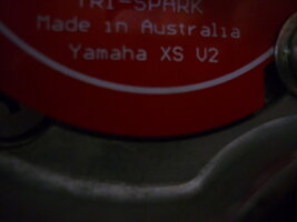
Shows the clearance mentioned above - apology poor photo
Consulted Steve - I mentioned that I had achieved .3mm by using the bit of clearance in the base plate and he said that’s OK and he would keep an eye (in manufacturing/design/engineering. on this part.
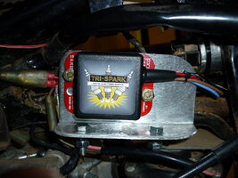
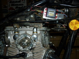
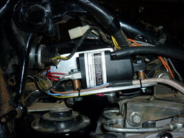
Shows the mounting of the control unit and coil
Excuse the state of my bike – it’s a barn find and I’m currently in the process of rewiring the lot.
The control unit is tiny and beautifully made.
Consulted Steve - is it okay to mount the control unit in such a hot position and close to the coil and he said that’s where he expects it to be mounted.
If mounting the coil using the original coil bracket/platform – stagger the mounting holes so the coil sits rearward to give tank tunnel clearance.
Wiring is very simple – excellent diagram in the instructions.
On my 77D the double female bullet connection, that was the active feed for the original coils, accepts the two red wires from the control unit and coil – neat and simple.
Check all your work and start the motor.
You need a strobe light to observe your timing - I bought a cheap one and it works fine.
You want to adjust the base plate so that the timing mark shows no further than the maximum advance mark when the motor is revved to 3000.
The timing mark at idle is not important – do not adjust to it – you will find it will be somewhere around it anyhow.
If you run out of adjustment on the base plate, just loosen the nut on the trigger rotor and rotate it a bit, reset the base plate to the middle of its slots and have another go.
Tighten the trigger rotor nut and base plate screws – don’t overtighten.
Spark Plugs:
The spark plug caps (that fit on the coil HT leads) are non resistor.
The Instructions call for resistor plugs e.g. BPR7ES.
Consulted Steve - you will achieve the strongest spark with non resistor caps and plugs and if you have no issues with "electrical noise" effecting (say) radios or digital meters then why not have the strongest spark available. Any issues with the above then use resistor plugs or caps.
I have tested with both and noticed no difference.
Summary:
Performance:
I rode tested my bike around the neighbourhood - I have not run it flat out for a period of time - I have opened the throttle fully at about 40 Klm/hr in top gear (maximum cylinder filling) and the bike just responded perfectly - I have accelerated to about 5000 rpm in some gears - when cold it cranks about 2 cycles before starting - when hot it starts instantly - seat of the pants dyno feels like its more responsive - this was very noticeable on the first ride ( Im used to it now) - so far testing has been excellent.
Unit:
Very well made – quality finish.
Very simple to install - in the perfect world with no interruptions and no messing around with coil brackets, it would take about 30 minutes.
Small control unit with backing plate for easy placement.
Infinitely adjustable to achieve timing.
Timely answers from Tri-Spark when I have contacted them.
More expensive than competition.
Instruction booklet has minimal instructions because you don’t need them – its uncomplicated.
Consulted Steve - suggest link to instruction book.
https://www.trispark.com.au/compass-ignition-for-yamaha-xs-650-1970-1985
https://www.trispark.com.au/assets/files/Compass Yamaha CS-0070.pdf
I have a new appreciation of the work involved in posting a thread like this. Hats off to all those who have done this the likes of Jim, Mailman, Twins, Gary and all thos I have not mentioned.
Regards Ray.
I recently fitted a Tri-spark electronic ignition to my Yamaha XS650D.
I purchased the unit from Steve at Tri-Spark who lives in the same city as me.
Disclaimer – I paid full retail price for it and advised Steve at Tri-Spark that I will do a “install and review” for the 650 Forum”.
Cost 450 A$.
I consulted Steve on a couple of points - wherever that is the case I will lead with the words "consulted Steve".
Apology - my 77D is a barn find - it is a work in progress - since the photos I have rewired the bike.
The text for each photo appears under the photo.
First Impression - nice packaging
The above 2 photos shows there’s not much too it.
It seems to be the minimum number of parts to make an electronic ignition.
They have kept it simple and uncomplicated.
At this stage I notice how well built/designed/engineered it is.
This is the base plate and the rotor trigger
The Base plate is around 3mm thick (strong) and fits where the points base plate used to.
The Rotor Trigger is nicely machined.
Set the timing marks on the rotor with the full advance mark on the stator.
This is very important.
This step confuses some people – look at it like this – you are simply telling the control unit that this is the maximum advance that it is allowed to achieve – the control unit will then deny this advance at idle RPM but allow that previously set maximum at around approx. 3000 RPM.
Remove the advance weights and springs.
Take off the points plate complete with points (2 screws) and remove the nut, on the end of the shaft and remove the breaker cam.
Pull out the rod, from the right side, that goes through the middle of the camshaft, and put the spring washer under the disc, that activated the weights, and push the rod back in.
Note – the disc will still be engaged with the original little pin that sticks out of the rod.
This photo shows the spring washer under the disc.
Fit the Tri-Spark base plate into the same recess where the points plate was and fit the 2 screws.
The 2 screws should be approx. in the middle of the adjustment slots in the base plate. Just nip the screws at this stage. (notice the screws aren’t in the middle of the base plate – by the time I took the photo I had timed my motor by turning the base plate – more of this later)
Fit the trigger rotor onto the shaft and secure with the original washer and nut – don’t fully tighten yet.
Note – the trigger rotor will engage with the original little pin that sticks out of the rod.
Turn the rod and trigger rotor so that one of the wings points to the middle of the button on the pickup.
OK – heres the first slightly technical point.
You want the wings on the trigger rotor to clear the button on the pickup by .5mm (half of 1 mm).
In my installation I had to use the little bit of play where the base plate fits into the recess by pushing the base plate over to one side. By doing this I was able to achieve .3mm.
If you look carefully at the next photo you will see the slight gap on the edge of the base plate – this bit of clearance was necessary in my installation.
Tighten the base plate screws and the nut retaining the trigger rotor – firm at this stage because some adjustment of the base plate may be required.
Shows the clearance mentioned above - apology poor photo
Consulted Steve - I mentioned that I had achieved .3mm by using the bit of clearance in the base plate and he said that’s OK and he would keep an eye (in manufacturing/design/engineering. on this part.
Shows the mounting of the control unit and coil
Excuse the state of my bike – it’s a barn find and I’m currently in the process of rewiring the lot.
The control unit is tiny and beautifully made.
Consulted Steve - is it okay to mount the control unit in such a hot position and close to the coil and he said that’s where he expects it to be mounted.
If mounting the coil using the original coil bracket/platform – stagger the mounting holes so the coil sits rearward to give tank tunnel clearance.
Wiring is very simple – excellent diagram in the instructions.
On my 77D the double female bullet connection, that was the active feed for the original coils, accepts the two red wires from the control unit and coil – neat and simple.
Check all your work and start the motor.
You need a strobe light to observe your timing - I bought a cheap one and it works fine.
You want to adjust the base plate so that the timing mark shows no further than the maximum advance mark when the motor is revved to 3000.
The timing mark at idle is not important – do not adjust to it – you will find it will be somewhere around it anyhow.
If you run out of adjustment on the base plate, just loosen the nut on the trigger rotor and rotate it a bit, reset the base plate to the middle of its slots and have another go.
Tighten the trigger rotor nut and base plate screws – don’t overtighten.
Spark Plugs:
The spark plug caps (that fit on the coil HT leads) are non resistor.
The Instructions call for resistor plugs e.g. BPR7ES.
Consulted Steve - you will achieve the strongest spark with non resistor caps and plugs and if you have no issues with "electrical noise" effecting (say) radios or digital meters then why not have the strongest spark available. Any issues with the above then use resistor plugs or caps.
I have tested with both and noticed no difference.
Summary:
Performance:
I rode tested my bike around the neighbourhood - I have not run it flat out for a period of time - I have opened the throttle fully at about 40 Klm/hr in top gear (maximum cylinder filling) and the bike just responded perfectly - I have accelerated to about 5000 rpm in some gears - when cold it cranks about 2 cycles before starting - when hot it starts instantly - seat of the pants dyno feels like its more responsive - this was very noticeable on the first ride ( Im used to it now) - so far testing has been excellent.
Unit:
Very well made – quality finish.
Very simple to install - in the perfect world with no interruptions and no messing around with coil brackets, it would take about 30 minutes.
Small control unit with backing plate for easy placement.
Infinitely adjustable to achieve timing.
Timely answers from Tri-Spark when I have contacted them.
More expensive than competition.
Instruction booklet has minimal instructions because you don’t need them – its uncomplicated.
Consulted Steve - suggest link to instruction book.
https://www.trispark.com.au/compass-ignition-for-yamaha-xs-650-1970-1985
https://www.trispark.com.au/assets/files/Compass Yamaha CS-0070.pdf
I have a new appreciation of the work involved in posting a thread like this. Hats off to all those who have done this the likes of Jim, Mailman, Twins, Gary and all thos I have not mentioned.
Regards Ray.


