Motor Timing with Pamco Electric Ign. & TC bro’s PMA kit

While I agree with that in principle... it'd be much easier to just move the marks to a point farthest away from the crank center. And mind what Gary said above... full advance is much more critical than the initial "F" mark. You really should include that.

View attachment 158822
While I agree with that in principle... it'd be much easier to just move the marks to a point farthest away from the crank center. And mind what Gary said above... full advance is much more critical than the initial "F" mark. You really should include that.

View attachment 158822


This is a solid idea Jim. Never thought it would have been less precise with the way I did it/ TC bro's tells you how to do it. Makes a lot of sense.
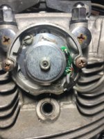
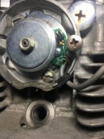
after all the questions I have asked and read over all of ya'll info I still have to ask a question. Mounting the rotor on to the crankshaft only goes on one way with the key. Making the marks is to see where you are in your timing. So if the bike was out of timing how do I make the adjustment? I had my valve covers off on intake and exhaust to watch valves move. Rotation of the crank allowed me to see the intake valve move down and back up to a stop. Next to see the exhaust valve do the same. Then the piston came back up and was up at TDC. Made my marks.
 
Your new rotor has no keyway and will install in any old spot, so the TDC mark you make is good ONLY until you take the rotor off again.
But no the camchain keeps the crank, cam and Pamco in correct alignment even with the rotor off.

My new rotor does have a Key. Came with one and needed it reinstalled. So that puts me in the same spot I was in before. I need to make new marks on my rotor and case. I am confused on how to make a adjustment if needed. I have the electric high output ignition ( no points) with the PMA. I can find TDC by removing the valve covers on Intake and Exhaust, rotating crank to TDC. ( see intake valve move down and back up to a stop & and same with the exhaust) Piston reaches top. Make my marks and that should be it right? Valves are adjusted. I just don't get how to adjust the system if it is outside of full advance 38 degrees?
 
While I agree with that in principle... it'd be much easier to just move the marks to a point farthest away from the crank center. And mind what Gary said above... full advance is much more critical than the initial "F" mark. You really should include that.

View attachment 158822


If I make the marks like you did. 15 degrees .500 inch ( 12.7mm) and 38 degrees in inches is what?
Mounting my rotor to the crank shaft with the key lines me up. I found TDC by rotating rotor and watching intake valve move down and back up to a stop and then the same with the exhaust. Piston reaches the top and there is TDC. Make marks on case and rotor.
If I run the bike and see it is out then I set it 180 out. start over and re mark. If that does not do me then how or what do I do to make my adjustments.
Electric ignition (no points) is set. Valves are set.
 
You'll need to open the points cover on the top left of left cylinder to find out what ignition you have. Take a pic of it so we can see. Then we'll know how to adjust it.
If I make the marks like you did. 15 degrees .500 inch ( 12.7mm) and 38 degrees in inches is what?
Can't answer that 'till we know the diameter of the rotor. Follow these instructions. When you find the distance, multiply that by 15 and 38 to find your answers.

A99C2D6E-5542-4575-9B93-CF5A08BBAB40.jpeg
 
You'll need to open the points cover on the top left of left cylinder to find out what ignition you have. Take a pic of it so we can see. Then we'll know how to adjust it.

Can't answer that 'till we know the diameter of the rotor. Follow these instructions. When you find the distance, multiply that by 15 and 38 to find your answers.

View attachment 158849
another amazing diagram attached tot he photo! Can't thank you enough for your patients and help to understand this. I will do my H.W and respond to you good sir. :)
 
You'll need to open the points cover on the top left of left cylinder to find out what ignition you have. Take a pic of it so we can see. Then we'll know how to adjust it.

Can't answer that 'till we know the diameter of the rotor. Follow these instructions. When you find the distance, multiply that by 15 and 38 to find your answers.

View attachment 158849


Okay here we go! going to supply Metric and Imperial.
Center of Crank hole to edge of case = 600mm (23.6 inches) Multiply that by 2 and I got 1200mmm (47.2 inches) Yes?
To get Circumference in Metric I divide by 3.1416 which = 3769mm (148.2 inches) (C)
Divide C. by 360 and I got 10.4mm (2.4 inches)
 
Photo’s of left side cylinder Electric Ign. As requested! :)
 

Attachments

  • 16EED115-3B0C-41B1-B0E4-7E477A25C9E2.jpeg
    16EED115-3B0C-41B1-B0E4-7E477A25C9E2.jpeg
    207.9 KB · Views: 155
  • 55E4025D-5ADC-4BA0-9248-BAA3CE781419.jpeg
    55E4025D-5ADC-4BA0-9248-BAA3CE781419.jpeg
    218.2 KB · Views: 181
  • 649FA414-43AF-4124-A03B-27BA6F405951.jpeg
    649FA414-43AF-4124-A03B-27BA6F405951.jpeg
    152.4 KB · Views: 158
If I mount the rotor to the crankshaft in the slot where it lines up with the key, then the new lines to mark TDC, Fire and Advance are just references. I rotated the rotor and found TDC. Clutch side (right side) valve springs can wiggle and my rotor side valves are tight with the piston at the top. Thats TDC. (I think) What am I missing? Should be able to start her up and see if it is right or 180° out right? Not sure how to make further adjustments. Jim I know you have to respond to my H.W. Assignment but just can’t get this out of my head. It might be hard to sleep tonight. Hah
:)
 
Also after the re wire process I have one wire loose. (Orange). It is coming off the coil pack to the electric ignition system. Has to be a negative. Have my positive established. Connect to negative assembly and can not toss a spark. Bike had great spark and compression before this re wire job started.
New plugs and all have been tested. Could it be something due to not having TDC. Not sure what this wire does. Lost in translation when removing all the old wiring. Coil pack can not be found online for reference to wire diagrams. Check photos below.
 

Attachments

  • 6980562E-6F13-4054-8215-3F6386F61627.jpeg
    6980562E-6F13-4054-8215-3F6386F61627.jpeg
    152.4 KB · Views: 128
  • BE76774B-CCAE-40F9-A792-3C0696334866.jpeg
    BE76774B-CCAE-40F9-A792-3C0696334866.jpeg
    89.4 KB · Views: 179
Also after the re wire process I have one wire loose. (Orange). It is coming off the coil pack to the electric ignition system. Has to be a negative. Have my positive established. Connect to negative assembly and can not toss a spark. Bike had great spark and compression before this re wire job started.
New plugs and all have been tested. Could it be something due to not having TDC. Not sure what this wire does. Lost in translation when removing all the old wiring. Coil pack can not be found online for reference to wire diagrams. Check photos below.
Your PMA rotor timing mark issues have no influence on the ignition system function. With a fully charged battery the ignition should work even with no alternator fitted. Assuming the ignition timing was set correctly with the stock alternator in place, any marks on the new PMA setup is only for future checks and adjustments of advance mechanism and ignition.
What coils do you have, stock or aftermarket ? The coil pic is not showing the whole coil, but it looks stock/oem to me. Maybe a new pic will help us help you further.

Got it. I think it just has been a long couple nights and I was thinking of everything. Didn’t think that it wasn’t tossing spark due to timing but I had to ask.
Secondly Yes the timing was set correctly prior to the new PMA kit install. So really I bolted that new rotor and on in the fixed (key) position and I am all set? Need spark and I should be on!
Completely re did the wiring, have new battery, new Alternator and new carbs. In theory this should run amazing now! Lol
Let’s hope so.
 
Get a digital voltmeter mount it where you can see it. Pamco's HATE high voltage. There's a lot of PMA's been sold with failure prone voltage regulators, they often go full charge full time when they fail. Feed a pamco 17-18 volts and you will let the smoke out. Keep some loads in the circuit, IE an incandescent headlight.
 
Your PMA rotor timing mark issues have no influence on the ignition system function. With a fully charged battery the ignition should work even with no alternator fitted. Assuming the ignition timing was set correctly with the stock alternator in place, any marks on the new PMA setup is only for future checks and adjustments of advance mechanism and ignition.
What coils do you have, stock or aftermarket ? The coil pic is not showing the whole coil, but it looks stock/oem to me. Maybe a new pic will help us help you further.

Pictures of Coil. It won’t give me a spark. Had miss fires before the big wire job. Maybe it died. Can I buy a coil pack only? Anyone know of one to get that will work with my set up in Victoria Australia? I will check Geoff’sXS. I believe stock had a dual coil set up. I would imagine whoever put this electric ignition on replaced the coil at the same time but then again maybe not.
 

Attachments

  • 8F9FCFF2-25E6-414F-B065-530D9DC186E5.jpeg
    8F9FCFF2-25E6-414F-B065-530D9DC186E5.jpeg
    144.4 KB · Views: 131
  • 8B5DE8B2-D547-4176-A2E6-C17291C631BF.jpeg
    8B5DE8B2-D547-4176-A2E6-C17291C631BF.jpeg
    126.7 KB · Views: 130
  • FB09E8D3-FFAB-4E80-AF14-8049DACC9E3E.jpeg
    FB09E8D3-FFAB-4E80-AF14-8049DACC9E3E.jpeg
    118.9 KB · Views: 135
  • 0CF966AB-93D6-42DB-9FF5-1175470183FB.jpeg
    0CF966AB-93D6-42DB-9FF5-1175470183FB.jpeg
    119 KB · Views: 135
Back
Top