My Summer 2021 Chopper Build 1976 XS650...but... a small issue

In your first post you mention installing a new tank. ..............Are the scorch marks for the tank brackets yours?.........were the electrics isolated when the welding was done?
Yes...those are my scorch marks ...and ..No..the electrics were not isolated (not sure what you mean by isolated ) ...I dont believe the electrics were compromised during my welding unless the grounding did something ...? Not sure .....interesting thought.
 
Small blue coil wires
 

Attachments

  • 20211108_171846.jpg
    20211108_171846.jpg
    193.9 KB · Views: 93
This is what my multi meter settings look like...and how I had my probes hooked.
 

Attachments

  • 20211108_173413.jpg
    20211108_173413.jpg
    176.6 KB · Views: 91
This is how I hooked up meter probes to coil wires....not sure if negative or positive is correct...?
 

Attachments

  • 20211108_171853.jpg
    20211108_171853.jpg
    174.4 KB · Views: 84
Do some learning, 
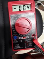
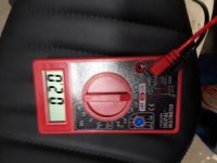
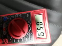
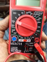
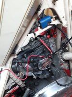
http://www.dansmc.com/electricaltesting.htm and learn to use a camera or check to make sure the pics you post are decent quality. You can check before posting and take some more if they are not flash

Isolating means to disconnect that part and isolate it. .....Google isolate

Welding without disconnecting battery, coils and especially an electronic ignition, means all the amps used in the welding are going through the bike and its components. If an electrical complainant is not designed for the amount of amps used when welding then they are going to be compromised............batteries can and will, (in some cases blow up................Acid then becomes your enemy.
That link is very helpful ..studying it already. ...AND ...I did not know all that about the welding...wow
 
If you had posted that pic 2 weeks ago some one would have noticed the burnt windings..........

Is that a CDI PMA system??

Looks so # 37 # 39 if the cooling fin thing on on picture in # 39 is the ignition box but the fins are 90 degrees turned in relation to # 37
That is ---- pre welding ignition Box
 
This may be a totally ignorant question but if the cap or hall sensor is bad how do you check that or am I way off on this system?
 
Not an expert on these systems and has never worked with them but have recently done some read up
As i Understand it you either have the condenser or battery

I installed a ... New fuel tank, New Fuel Line, New Spark Plugs, New Battery .

From MIkes

Battery Eliminator Capacitor Kit for XSCharge™ XS650 PMA (Permanent Magnet Alternator). Use this capacitor in place of your battery when installing our XSCharge™ XS650 PMA kit for Yamaha XS650. This will convert your bike to a battery-less charging system with kick only starting.

So if this is right no capacitor is on the bike.
 
A couple of things here. First the stator. there are two separate circuits in the stator. One provides power to charge the battery and the the other provides a high voltage to fire the coil. Hugh's system is pretty simple on the ignition side. A charge coil, the CDI control box, the ignition coil and plug wires. It is common for the battery charging coil to short internally because of the high currents and heat. It would not prevent the bike from starting because the two circuits are independent. The ignition charging coil is not that stressed and rarely fails but is something to check.
In a conversation with Hugh several years ago he mentioned pulling one wire on the relay would prevent the kill switch from grounding.
The nice thing about the CDI system is that if the engine turns it will make spark.


The other item is the flying height (gap) for the timing pickup. In Hugh's install guide are instructions on setting that gap.

The two things that need to be checked with the VOM are the charge coil under the flywheell and the timing pickup coil.
One note is be careful with leads from the charge coil. It can produce several hundred volts and can zap you pretty good.
 
This may be a totally ignorant question but if the cap or hall sensor is bad how do you check that or am I way off on this system?

The timing pickup is a simple coil mounted outside of the flywheel at about the 2 o'clock. you can disconnect the pickup coil and check for resistance.
 
Is it just me but to give effective help the paperwork would help
The installation manual
The circuit Schematic is sometimes necessary. At least if it shall be solved in reasonable ( free ) time
There is a relay as it seems but with no schematic it becomes guesswork .
For everyone except those who have installed it .
And specs of the coil resistance and so. .
Generally speaking pictures and videos helps
 
All the Stater coils are burnt...........should be a nice copper colour

View attachment 201364

Well spotted .. Common is then ( What I have heard without working with these systems ) is that the regulator has also fried first ..There are different types with different capabilities.
Shunt and Series .Regulators
The shunt feeds back power when regulating and heats up the parts.
So installing a new Stater without regulator can make one look sad an poor rather soon
 
Back
Top