New Tool in the Workshop

Signal

XS650 Guru
Top Contributor
Messages
1,414
Reaction score
4,385
Points
263
Location
New Zealand
Inspired by Jack’s D porting thread and after a very long gestation period my flow bench is almost finished.

I had the good fourtune to meet a kind and generous tuner who showed me his home made bench and gave me his spread sheet programme to crunch the numbers. My bench is basically a copy of his.

I intend to try some things that guys who are doing up the top end of their bikes might do and compare them to a stock head. Then follow Jacks how to guide. Eventually I will compare this to a Lilly Replica head I have earmaked for a special engine.
Disclaimer I know very little about porting but have a couple of orphan heads (no matching cover) to learn on.
This is in the future at the moment I am grappling with Fusion 360 to draw a valve depressor tool so I can 3D print it. I also need to build a riser for the plenum.

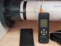
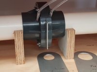
Flow Bench.jpg
Temp Sensor.jpg Metering Valve.jpg
 
Well this should be interesting. :geek:

Indeed. I'll almost certainly never port anything, but I love home made ways to get things done!

And OP, I hear ya on "grappling" with Fusion 360. I downloaded it intending to learn how to use it but quickly decided I didn't need the aggravation for the little bit of 3D design that I do.
 
Downeaster Fusion 360 has far more functions than I can ever imagine to use. The truth is I got the 3D printer as a stepping stone to a CNC router (which I cant justify the outlay at the moment).
The idea was to become familar with G code and tool paths and designing in 3D.
What I have found however is that the programs work together so well that at this stage anyway I haven't needed to alter much anything.
The 3D printer will work well with the flow bench allowing me to make and try different velocity stacks, and carb spigots.
The trouble at the moment my design skills are not keeping up with my imagination.
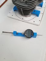
I have printed a DTI holder for the valve depressor now designing the bracket to fix it to the head.
 
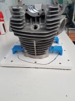
This week to make a riser I took the liners out of a ruined barrel and cut one down to flush with the bottom edge.

After polishing the outside of the liner, it is an easy sliding fit in the barrel now. In future there may be a need to swap it for a larger bore.
The barrel was given a quick trip to the blasting cabinet to clean it up.

I cut some thick paper base and head gaskets and fixed the barrel down using some printed brackets and bolted the head to the barrel using the 2 bolts under the spark plugs.
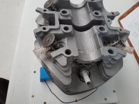
I did a quick test and found at 28 inches of vacuum with light springs on the valves they were being sucked open . I cut some reinforced tube to wedge under the top retainer to jam the valves closed.
Need to make a bracket for the valve depressor and some scale pointers for the inclined manometer and should be good to go.

I contacted my mentor, and he is going to make a calibration plate for his bench and send it to me so we can see how they compare as there are a few small differences between our benches.
Flow bench 5.jpg Flow bench 56.jpg Flow bench 567.jpg
 
The bench is pretty much all set to go. Just haven't been able to make time to do some testing. I am a bit of a project butterfly and have lots on the go at once.
I will post photos and results when I have some.
I solved the too weaker spring problem by using 2 of then per valve. I had 4 for setting up cams.
 
Back
Top