Discussing electronic ignitions, a topic that's surfaced here and there in the past, came up. Some of the ignition components on older motorcycles have nasty electrical habits, that result in a less than pristine +12 wandering around the wiring harness. Some components we add to the bike and some stock components can be hurt by these electrical nasties. I know nothing! But I got a bit of coaching from a few of those with the technical background to make suggestions. Here's some excerpts from @Paul Sutton
I read recently that when the coil fires it produces several (tens of) thousands of volts in the secondary for the spark and a couple of hundred volts in the primary winding i.e. the 12V+ side. So the coil can pollute the 12V+ line. On an Ebay listing I read that the rectifier should be rated higher than 400V because of the voltage induced in the primary winding. I have successfully used 19V TVS Diodes to protect electronics against these spikes.
Here is a diagram showing TVS Diode charactistics:
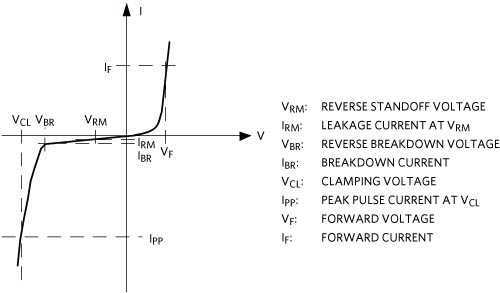
A TVS Diode is similar to a normal diode except it becomes conductive when you exceed a preset low voltage in the negative range where as a normal diode stays non-conductive in the negative range until you exceed the diodes max voltage rating which is often several 100 to a thousand volts.
The TVS Diode conducts in reverse as you approach Vcl. Although there is a TVS Diode rated at 14V it will be conducting significantly from about 12V so no good for auto-electricals. I settled on the 18V version because my regulator stays below 14.6 volts (14.3V with headlight on).
To remove over-voltage spikes from the power supply you just connect the TVS Diode in reverse bias between the 12V+ connection and ground. This is similar to when you reverse bias a normal silicon diode across a relay to short any induced spikes to ground.
The type I used: https://www.ebay.com/itm/RLA-P6KE18...141799?hash=item2567048e67:g:KOwAAOSwqYhZ2-SJ
I hope this helps.
Simple Diagram:
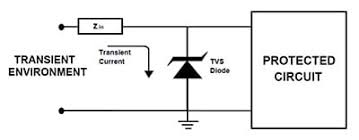
The reverse bias bit is all taken care of in the labelling of the TVS Diode. As shown in the two diagrams above the Band printed on the diode connects to the +12V. I also just checked how I wired mine in the Virago low fuel circuit and it is also the Band to the +12V. In the low fuel circuit the Op Amps would last about 2 minutes but with the TVS Diode added to the circuit the Op Amp has lasted almost 1 Year now.
I used the TVS Diode because they are designed for this job.
If it is stated not to use the +12V wire from the coil then do not use it. The TVS Diode is trimming off voltage greater than approx. 16 - 18 Volts. I believe the coil produces negative voltage spikes and perhaps some ringing. On my Virago to protect against -ve spikes I also put a regular silicon diode (1N4007) in parallel with the TVS Diode.
On my XS650SH I put silicon diodes across the relays, starter solenoid and the alternator field winding. These modifications have been mentioned several times from others on this forum - it is not my idea, just useful information shared by others. I made these modifications because my onboard voltmeter blew after about 20 miles riding. The diodes solved with problem.
And from @TwoManyXS1Bs
"The coil's inductive kickback voltage is quite high at the grounding side. But that's because the current has nowhere to go.
The same kickback currents appear on the coil's positive side, but that side is connected to the bike's power, with a buncha stuff to help absorb the current spike, keeping the voltage down. There'll still be a bit of a voltage spike there, but not as bad.
A trick used on cars back in the day was to simply add a condenser (capacitor) directly to the coil's positive connector, the other condenser wire (or body) grounded. Maybe you remember seeing some of those. Some cars came with this "suppressor" factory installed. Helped reduce power-line induced radio static. So, yes, there's a history of this nastiness occurring way back then.
Another trick I've not seen would be to feed power to the coil thru a rectifier diode, like the 6-amp 6A10. This would prevent positive kickback spikes from getting back into the power system. But, there'll be a voltage drop across this diode, somewhere around 1 volt."
Adding a capacitor right at the ignition module's power line would also help. Especially if the Tytronic doesn't have one built-in. Have a look at Sleddog's TCI schematics, find where +12v power comes in, look for the first capacitor on that feedline. I'd reckon that a minimum of 10 uF, 25v rated electrolytic cap would be used there. Capacitor filtered power inputs are quite common on automotive 12v gadgets...
So there's kinda two schemes? and they are a bit overlapping, put down a door mat to keep a component with dirty feet from making an electrical mess in the harness, or putting booties on the component you wish to protect.
I kinda like the door mat and I f my extremely limited lecricical no-ledge grocs this, these components will act as general buffers whether they are located at source or destination as long as they are in the loop?
I go looking to buy say 25 of each of the components Paul suggests to make up some electrical condoms.
P6KE18A+
TVS Diode, P6KE Series, Unidirectional, 15.3 V, 25.2 V, DO-204AC, 2 Pins
and
1N4007 - Standard Recovery Diode, 1 kV, 1 A, Single, 2.6 V, 30 A
and get deluged with different manu's, and specs, NONE of which I understand, add to it the usual shipping tax etc mysteries. any of the sub specs make a difference I need to worry about?
OK gggGary again;
I would like to hear, see? a best practices layout of these parts, assembled into a plug n play jumper, easily added here and there as needed for the spiffiest XS650 clean 12 volt fortress we can devise.
A few questions;
How long do I leave the leads, do I have to worry about just grabbing my 250 watt iron and globbing on some 22 gauge leads, with bullets and a ground ring? Can I slap the resulting stuff inside some heat shrink, hang it from the electrical connections and call it done? Can I test to be sure this is working? what would a good set up look like?
Hellpp?
I read recently that when the coil fires it produces several (tens of) thousands of volts in the secondary for the spark and a couple of hundred volts in the primary winding i.e. the 12V+ side. So the coil can pollute the 12V+ line. On an Ebay listing I read that the rectifier should be rated higher than 400V because of the voltage induced in the primary winding. I have successfully used 19V TVS Diodes to protect electronics against these spikes.
Here is a diagram showing TVS Diode charactistics:
A TVS Diode is similar to a normal diode except it becomes conductive when you exceed a preset low voltage in the negative range where as a normal diode stays non-conductive in the negative range until you exceed the diodes max voltage rating which is often several 100 to a thousand volts.
The TVS Diode conducts in reverse as you approach Vcl. Although there is a TVS Diode rated at 14V it will be conducting significantly from about 12V so no good for auto-electricals. I settled on the 18V version because my regulator stays below 14.6 volts (14.3V with headlight on).
To remove over-voltage spikes from the power supply you just connect the TVS Diode in reverse bias between the 12V+ connection and ground. This is similar to when you reverse bias a normal silicon diode across a relay to short any induced spikes to ground.
The type I used: https://www.ebay.com/itm/RLA-P6KE18...141799?hash=item2567048e67:g:KOwAAOSwqYhZ2-SJ
I hope this helps.
Simple Diagram:
The reverse bias bit is all taken care of in the labelling of the TVS Diode. As shown in the two diagrams above the Band printed on the diode connects to the +12V. I also just checked how I wired mine in the Virago low fuel circuit and it is also the Band to the +12V. In the low fuel circuit the Op Amps would last about 2 minutes but with the TVS Diode added to the circuit the Op Amp has lasted almost 1 Year now.
I used the TVS Diode because they are designed for this job.
If it is stated not to use the +12V wire from the coil then do not use it. The TVS Diode is trimming off voltage greater than approx. 16 - 18 Volts. I believe the coil produces negative voltage spikes and perhaps some ringing. On my Virago to protect against -ve spikes I also put a regular silicon diode (1N4007) in parallel with the TVS Diode.
On my XS650SH I put silicon diodes across the relays, starter solenoid and the alternator field winding. These modifications have been mentioned several times from others on this forum - it is not my idea, just useful information shared by others. I made these modifications because my onboard voltmeter blew after about 20 miles riding. The diodes solved with problem.
And from @TwoManyXS1Bs
"The coil's inductive kickback voltage is quite high at the grounding side. But that's because the current has nowhere to go.
The same kickback currents appear on the coil's positive side, but that side is connected to the bike's power, with a buncha stuff to help absorb the current spike, keeping the voltage down. There'll still be a bit of a voltage spike there, but not as bad.
A trick used on cars back in the day was to simply add a condenser (capacitor) directly to the coil's positive connector, the other condenser wire (or body) grounded. Maybe you remember seeing some of those. Some cars came with this "suppressor" factory installed. Helped reduce power-line induced radio static. So, yes, there's a history of this nastiness occurring way back then.
Another trick I've not seen would be to feed power to the coil thru a rectifier diode, like the 6-amp 6A10. This would prevent positive kickback spikes from getting back into the power system. But, there'll be a voltage drop across this diode, somewhere around 1 volt."
Adding a capacitor right at the ignition module's power line would also help. Especially if the Tytronic doesn't have one built-in. Have a look at Sleddog's TCI schematics, find where +12v power comes in, look for the first capacitor on that feedline. I'd reckon that a minimum of 10 uF, 25v rated electrolytic cap would be used there. Capacitor filtered power inputs are quite common on automotive 12v gadgets...
So there's kinda two schemes? and they are a bit overlapping, put down a door mat to keep a component with dirty feet from making an electrical mess in the harness, or putting booties on the component you wish to protect.
I kinda like the door mat and I f my extremely limited lecricical no-ledge grocs this, these components will act as general buffers whether they are located at source or destination as long as they are in the loop?
I go looking to buy say 25 of each of the components Paul suggests to make up some electrical condoms.
P6KE18A+
TVS Diode, P6KE Series, Unidirectional, 15.3 V, 25.2 V, DO-204AC, 2 Pins
and
1N4007 - Standard Recovery Diode, 1 kV, 1 A, Single, 2.6 V, 30 A
and get deluged with different manu's, and specs, NONE of which I understand, add to it the usual shipping tax etc mysteries. any of the sub specs make a difference I need to worry about?
OK gggGary again;
I would like to hear, see? a best practices layout of these parts, assembled into a plug n play jumper, easily added here and there as needed for the spiffiest XS650 clean 12 volt fortress we can devise.
A few questions;
How long do I leave the leads, do I have to worry about just grabbing my 250 watt iron and globbing on some 22 gauge leads, with bullets and a ground ring? Can I slap the resulting stuff inside some heat shrink, hang it from the electrical connections and call it done? Can I test to be sure this is working? what would a good set up look like?
Hellpp?
Last edited:


