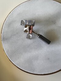
I am thinking right or wrong a short inside the regulator
So even the same rotor can draw different current .depending on how the top contact in the regulator connects.
And if other problems inside the regulator
There is a bypass resistor so if the contact dont land / connect as it should . Which happens with points also. that can affect
As the picture in post #41
Full connect a short brown to green
Not connected at the top it goes through the resistor but not open circuit if the resistor is not broken.
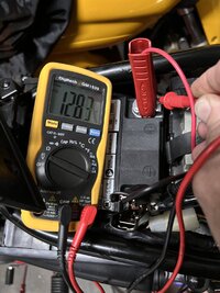
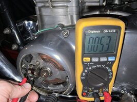
Andy can verify with his meter what the slip rings measure .Even if his meter has a low battery
it should give info .
By the way I do know i keep on like a demented parrot about the regulator. Cant we for now call it Experience.
I can change my mind if i need to .But I have had problems with these 3 or 4 of them One winter .Before I gave up
To much work with no success
View attachment 235385